
Chilled water and humid rooms are a bad mix. When a surface drops below the room dew point, water forms on pipes, valves and grilles, and the callback lands on the fan coil brand. This guide explains how to specify a fan coil thermostat with dew point sensor for OEM fan coil ranges: which readings you need, how the anti-condensation sequence works, which Modbus points to expose and how to order it, using the published Alledio Thermostat and its built-in humidity sensor as the reference.
White LabelFCUOEMHVACHumidityTemperature

Why OEMs ask for dew point control on a fan coil
A standard fan coil is built to condense. Water forms on the cold coil, runs into the drain pan and leaves through the condensate line. The trouble starts outside the drain pan: on an uninsulated valve body, a cold supply pipe in the ceiling void, or the casing and discharge grille when the fan stops while chilled water keeps flowing.
Heat pump projects raise the stakes. Many systems now run higher chilled-water temperatures for efficiency, and some combine fan coils with radiant ceilings or floor cooling that must stay dry. In those designs the controller has to know the room dew point and keep every cold surface above it, or the efficiency gain turns into stained ceilings.
That is why the question appears in OEM briefs. Product managers want one wall device, a true fan coil thermostat with dew point sensor, that measures the room, protects the unit and reports to the BMS, instead of a thermostat plus a separate humidity transmitter. For the wider product choice, the room unit vs thermostat guide explains when a relay thermostat is the right wall device at all.
How a fan coil thermostat with dew point sensor measures the room
There is no separate dew point element in a wall device. Dew point is calculated from two readings, air temperature and relative humidity, using a standard approximation such as the Magnus formula. A thermostat with a built-in humidity sensor therefore has everything it needs on the wall.
Accuracy follows from the sensors. The Alledio Thermostat publishes ±0.2 °C for temperature and ±1.8 %RH for humidity. At 24 °C and 50 %RH the dew point is about 12.9 °C, and those tolerances keep the calculated value within roughly ±0.7 K, which is tight enough for a safety margin of 2 to 3 K.
| Dew point input or action | Published on the Alledio Thermostat | What to write in the RFQ |
|---|---|---|
| Room temperature | Built-in digital sensor, ±0.2 °C (0-60 °C) | Sets the accuracy of the dew point you calculate |
| Room humidity | Built-in digital sensor, ±1.8 %RH (10-90 % at 25 °C) | The second input of every dew point formula |
| Surface or pipe temperature | 1× NTC input on every I/O model | Clamp the probe on the chilled-water supply pipe or coil header |
| Cooling output | 2 × 0-10 V, 2 × digital output, 1 + 1 mixed, or 2 × relay H/C | Pick the model that matches the cooling valve |
| Fan | Relays for three fan speeds: 1 / 2 / 3 / auto / off | Define fan run-on and fan-valve interlock times |
| Bus | RS-485 Modbus RTU, client or server, address 1-247 | List the dew point and alarm registers you want exposed |
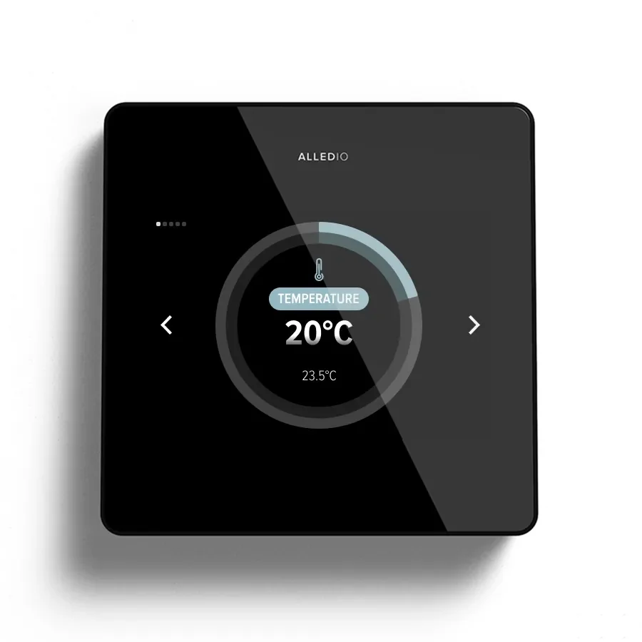
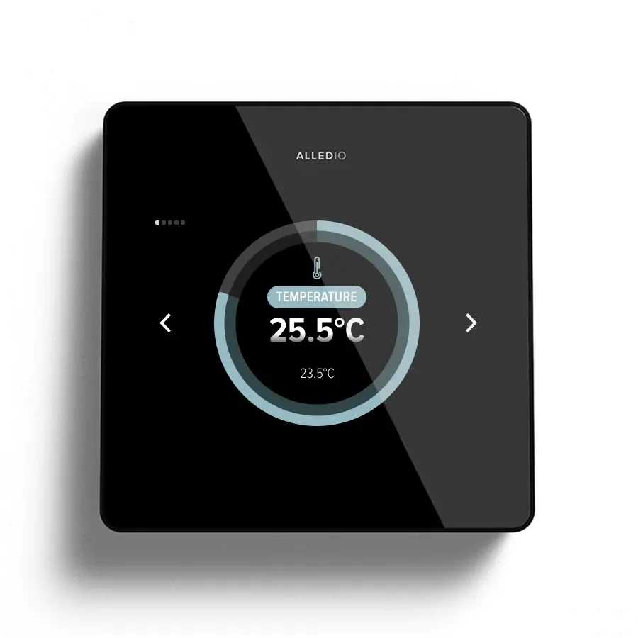
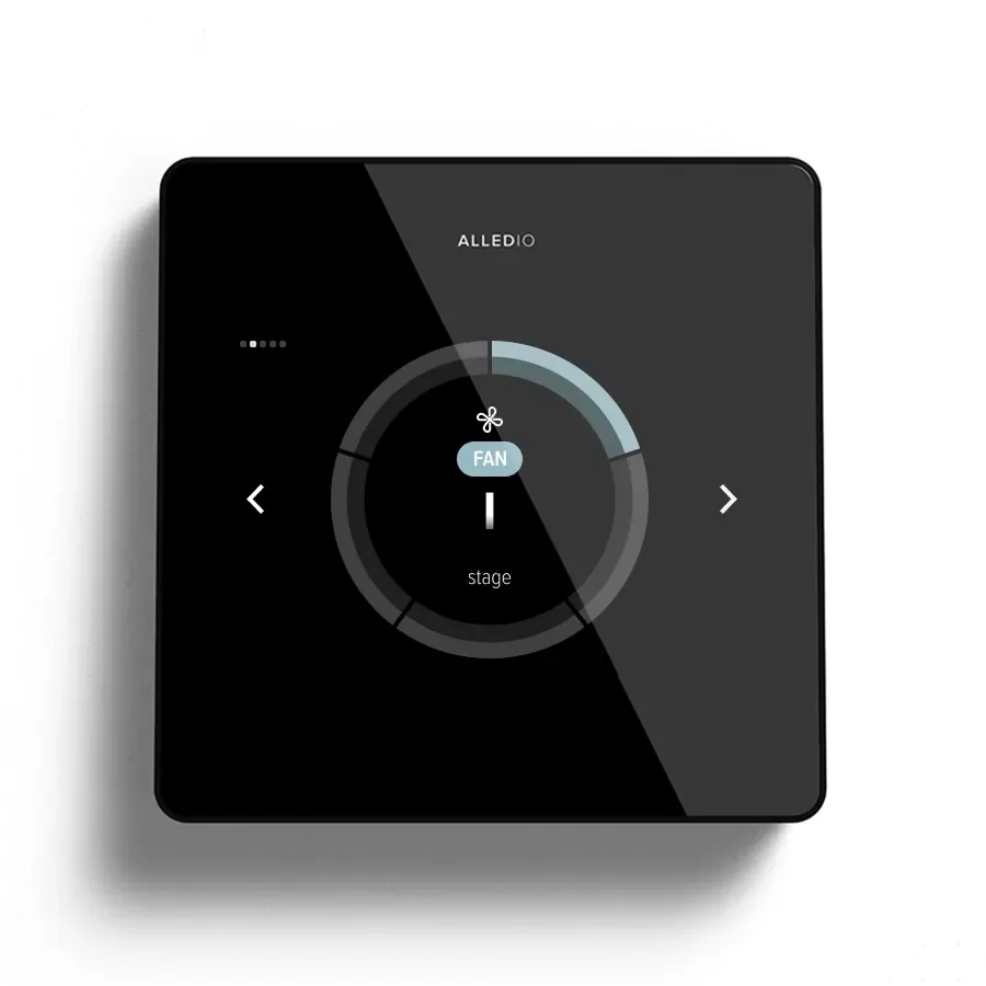
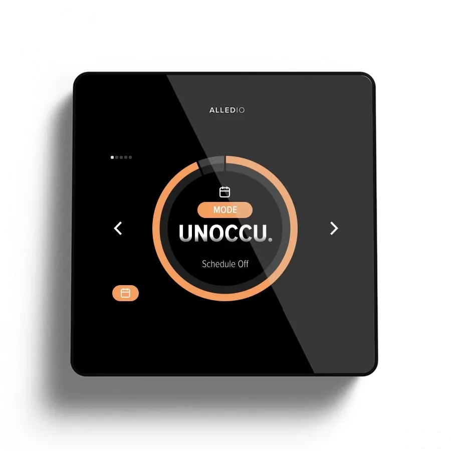
| Display | 3.5 inch 480 × 320 capacitive glass | Decide whether occupants see humidity or only an alarm icon |
The calculation and the sequence that uses it live in firmware. The Thermostat page lists humidity control and dehumidification among its HVAC features, and Alledio integrates requested functions into the OEM firmware profile. Treat the dew point logic as part of that profile, quoted with your project, or compute it in the BMS from the humidity and temperature registers.
If you need a dew point value calculated on the device and published as a ready register today, the Alledio Multi-Sensor computes dew point, enthalpy and air density on board. The Modbus multi sensor OEM guide shows how that node pairs with a fan coil thermostat on the same RS-485 trunk.
Reference fan coil configurations
2-pipe with a modulating cooling valve
A 2-pipe unit with a 0-10 V valve uses the 2 × AO model. One output drives the valve, the NTC input reads the supply pipe, and the dew point margin limits the valve opening before the pipe surface reaches the room dew point. The 2-pipe fan coil article covers the changeover side of this layout.
4-pipe with separate heating and cooling
In a 4-pipe unit the cooling valve is the only one that matters for condensation. The 2 × relay H/C model suits thermal actuators, while analogue models suit modulating valves. Read the 4-pipe fan coil guide for sequencing, then add the dew point limit as one extra condition on the cooling output.
Fan coil plus radiant cooling
When a radiant ceiling shares the room with a fan coil, the fan coil becomes the dehumidifier. The thermostat runs the fan coil with a cold coil to remove moisture while the BMS raises the radiant water temperature to stay above dew point. This split works best when the room humidity and calculated dew point are both visible on Modbus.
Wiring and the anti-condensation sequence of operation
The Thermostat runs on 230 VAC and mounts flush in a standard EU Ø60 mm box, so it uses the same back box as a light switch. Every I/O model carries the NTC input, the three fan relays and the Modbus terminals.

On the 2 × relay H/C model shown above, the upper block takes L, N, the NTC probe and Modbus A, B and GND. The lower block carries the heating and cooling relays and the fan relays R1, R2 and R3 with their common. For dew point work, the NTC terminal is the key: it brings the cold surface temperature into the same device that measures the room air.
A practical sequence for a fan coil thermostat with dew point sensor uses four interlocks, each one a parameter you can write into the firmware specification:
- Fan-valve interlock: the cooling valve closes whenever the fan is off, so the casing never runs cold without airflow.
- Dew point margin: if the NTC pipe temperature falls within a set margin of the room dew point, the valve is limited or closed.
- Dehumidify mode: when humidity is high but the room is cool, the fan runs on a low stage with the valve open to remove moisture.
- Alarm and report: a condensation-risk flag is raised on screen and on Modbus for the BMS.
A drain pan float switch is not a published input on the Thermostat. Wire it into the unit's safety chain, or move to the Alledio OEM Room Controller when you need universal inputs on the controller. Where fan relays must live inside the unit, the Modbus relay extender pattern keeps mains switching off the wall.
Modbus points to agree for dew point control
Integrators want the same points in every room. Agree a frozen register map before the first sample ships, and include the dew point items next to the usual comfort points:
- Room temperature and relative humidity, read-only.
- NTC surface temperature and the calculated dew point, if the firmware profile includes it.
- Dew point margin and dehumidify thresholds, writable by the BMS.
- Cooling valve command, fan stage and the active interlock state.
- Condensation-risk alarm, probe failure and communication loss.
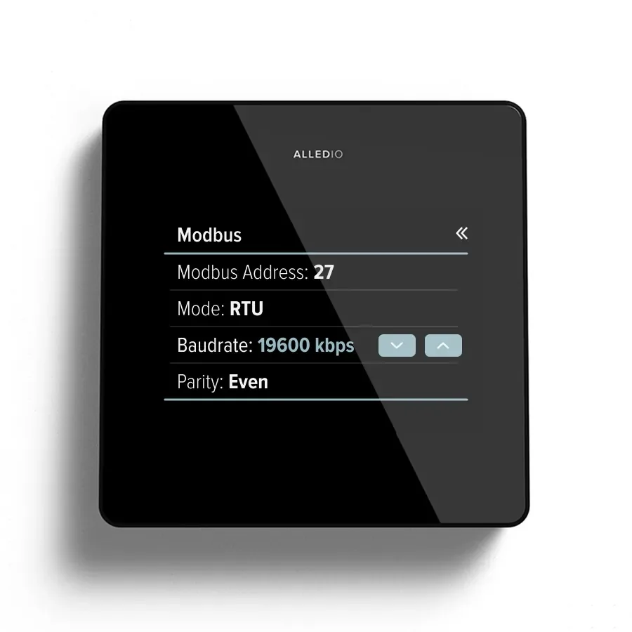
The Thermostat speaks RS-485 Modbus RTU as client or server, at addresses 1 to 247 and baud rates up to 115200, with ¼ unit load for up to 128 devices per segment. Test the map on the bench with Modbus Mate, a free browser tool, before you freeze the point list. BACnet is not in the standard firmware; the BACnet wall multi-sensor article covers that route.
Humidity data also feeds energy decisions beyond condensation. The article on enthalpy in AHUs shows how the same temperature and humidity pair supports economiser logic upstream of the fan coils.

OEM branding, MOQ and NRE
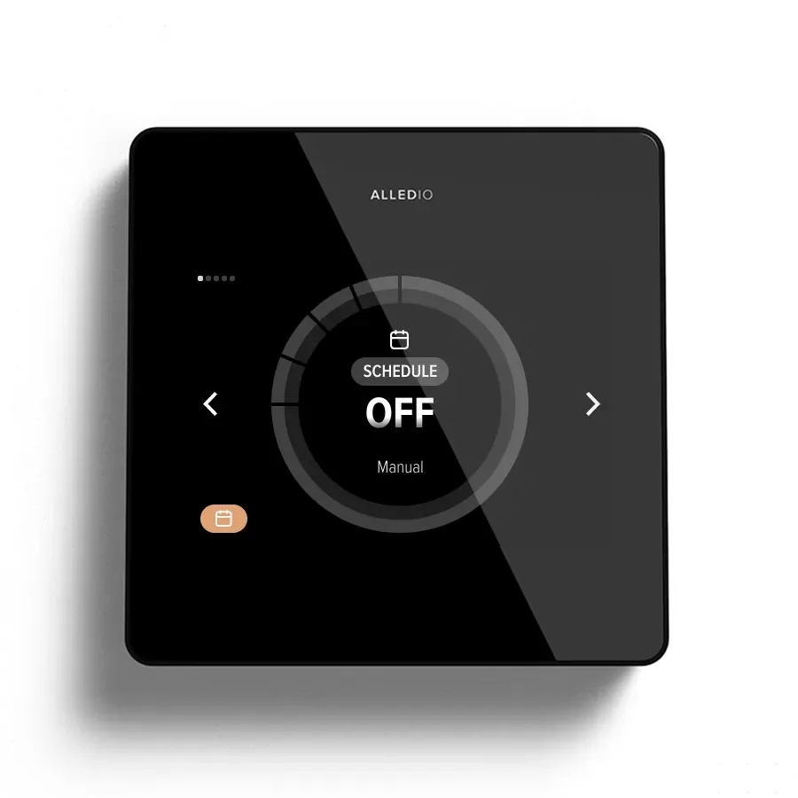
The Thermostat ships in white, black and silver with ABS and scratch-resistant glass, and the OEM version carries your logo and UI theme. The white label FCU thermostat article shows how a branded SKU is defined, and the 3-speed FCU OEM thermostat guide lists the RFQ fields purchasing will ask for.
Commercially, Alledio works OEM-only. MOQ is 1,000 pcs per order and negotiable, and firmware work such as a dew point sequence is quoted separately as NRE. Larger changes can run through hardware and software development services, keeping the standard hardware wherever possible.
Compliance stays as published: CE with EN 60730-1, EN 60730-2-9 and EN 300 328, IP20 and an operating range of −10 to +50 °C at up to 85 %RH non-condensing. Put these on the submittal sheet and take any further declarations from the product documents.
FAQ
Does this apply to my fan coil platform?
If your units use three-speed fan motors and a heating or cooling valve, yes. Choose the I/O model that matches the valve, and use the NTC input for the cold surface temperature.
Can I skip the Room Unit or Multi-Sensor?
Usually yes. The Thermostat already measures temperature and humidity, which is enough for a firmware or BMS dew point calculation. Add the Multi-Sensor only when you need dew point calculated on board or extra IAQ data in another location.
Does it support BACnet MS/TP?
Not in the standard firmware, which is Modbus RTU. Custom BACnet integration can be scoped on request for the datapoints you need.
What are the MOQ and NRE?
MOQ is 1,000 pcs per order and negotiable. Firmware changes, including a dew point sequence, are quoted and billed separately from the unit price.
Can we get samples to test the sequence?
Yes. Samples are purchased and ship with demo or test firmware, so your lab can run humidity and condensation tests before the OEM firmware is agreed.
Where is it made, and which approvals does it carry?
Alledio products are designed in Slovenia and manufactured in the EU. The Thermostat lists CE with EN 60730-1, EN 60730-2-9 and EN 300 328; check the declaration of conformity for the full list.
What to do next
Write the dew point margin, the interlocks and the register map into your RFQ, then compare them with the Alledio OEM Thermostat page and the Alledio Room Unit for relay-free variants. Start an OEM conversation or contact the team to request samples with demo firmware and a quote for your fan coil thermostat with dew point sensor range.