The JOY Fancoil 5DO is Thermokon's fan coil room controller for one of the most common jobs in HVAC: a fan coil with a three-speed AC fan and two on/off valves, one for heating and one for cooling. It puts five switching outputs in the wall unit. If you build fan coils or specify them and want to cover the same application with Alledio, the answer is a two-part setup: the Alledio Room Controller on the wall and the MX-EXT5 Modbus relay extender on a DIN rail at the fan coil. This article compares the two 1:1: what each one does, how the outputs map, where the specs differ, and who should choose which.
Part 1 of 5 in our Thermokon JOY vs Alledio series. Each part takes one JOY model and rebuilds the same application on Alledio.
Fan Coil3-SpeedOn/Off ValvesModbus RTU24 VOEMComparison
The short answer
- Same job: three fan speeds plus a heating and a cooling valve (or one change-over valve on 2-pipe units).
- Alledio setup: Room Controller RC-TH-2 + MX-EXT5 in Mode 1. Fan speeds on O1–O3, valves on O4 and O5. If you need no wired inputs at the wall, the Room Unit RU-TH-0 drives the MX-EXT5 just as well.
- Biggest difference: the 230 V JOY Fancoil 5DO switches the loads in the wall unit. With Alledio only 24 V and one Modbus pair go to the wall; the relays sit next to the loads.
- Where JOY leads: one single device, a choice of BACnet, KNX, EnOcean and LoRaWAN versions, and JOY Custom from 100 pieces.
- Where Alledio leads: 3.5" capacitive touchscreen, ±0.5 °C temperature accuracy, humidity as standard, 5 A relays, Wi-Fi and MQTT, setup on the device itself, and full OEM customisation of the UI and firmware.
JOY Fancoil 5DO vs Alledio at a glance
| Feature | JOY Fancoil 5DO (230 V, RS485 Modbus) | Alledio Room Controller + MX-EXT5 |
|---|---|---|
| Devices | 1 wall unit | Wall unit + DIN-rail relay module |
| Mains at the wall | Yes, 85–260 V~ and five switched lines | No, 24 V and one Modbus pair |
| Fan outputs | 3 NO, max. 3 A | 3 NO on the MX, 5 A at 250 V AC resistive, interlocked |
| Valve outputs | 2 NO, max. 500 mA | 2 NO on the MX, 5 A at 250 V AC resistive |
| Display | 2.5" LCD with touch-sensitive buttons | 3.5" capacitive touchscreen |
| Humidity | Optional | Standard |
| Custom versions | JOY Custom: buttons and logo, from 100 pcs | Full OEM: brand, UI, firmware, sensors, from 1,000 pcs |
What the JOY Fancoil 5DO does
According to Thermokon's datasheet (JOY FC 5DO RS485 Modbus, issue 13.05.2026, A165), the JOY Fancoil 5DO is a flush-mounted fan coil room thermostat "tailored for two-pipe and four-pipe fan coil units with two-wire electric valves". The facts that matter for this comparison:
- Outputs: three normally open contacts for the fan speeds (240 V, max. 3 A) and two normally open contacts for heating and cooling (240 V, max. 500 mA; triac outputs according to Thermokon's product page).
- Supply: 85–260 V~, max. 2.5 VA.
- Inputs on the Modbus version: DI1 for an NTC10k sensor or a floating contact, DI2 for a non-floating 230 V signal. Standalone versions have a third input.
- Control: integrated PI and 2-point/3-point controllers, plus a second 2-point control loop.
- User interface: 2.5" LCD (240 × 160 px) with a touch-sensitive glass front, 3 time programs with 4 periods each.
- Housing: PC and glass, black or white, IP30, 140 × 78 × 35 mm, for a standard EU flush box (Ø 60 mm).
The same 5DO model comes in several interface versions: standalone, RS485 Modbus, RS485 BACnet MS/TP, KNX, EnOcean and LoRaWAN. The interface doesn't change the I/O job, so this comparison holds for all of them.
The Alledio configuration that covers the same job
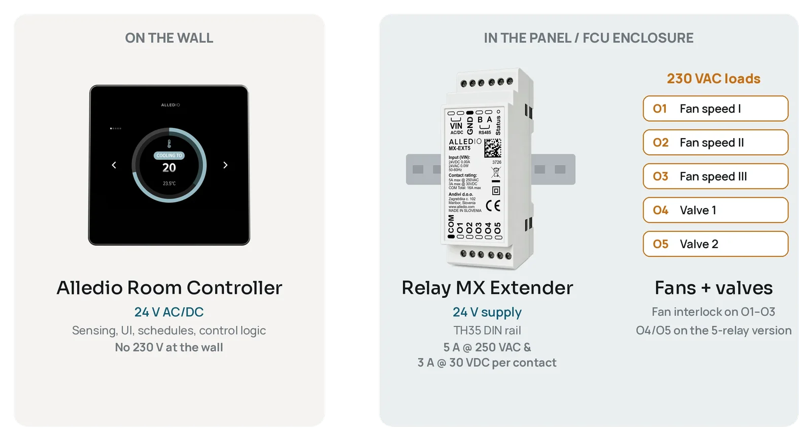
Alledio splits control and power into two devices. Together they are sold as the Alledio Thermostat: one wall device and one Relay MX Extender per room, on one 24 V supply and one Modbus line.
Parts list
| Part | Role | Setting for this use case |
|---|---|---|
| Alledio Room Controller RC-TH-2 | On the wall: temperature and humidity sensing, touch UI, schedules, control logic, Modbus to the BMS | 2 universal inputs (UI1, UI2) for a like-for-like input count with the JOY. Use RC-THC-2 if you also want CO₂. |
| Relay MX Extender MX-EXT5 | On the DIN rail at the fan coil: switches the 230 V fan and valves | Mode 1 (fan coil), which is the factory default |
The device codes are the ones shown in the Alledio Use Case Simulator. Each code says what is on board: RU is the Room Unit, RC the Room Controller, TH means temperature and humidity, THC adds CO₂, and the number is the I/O set.
| Code | Device | Sensors | Local I/O |
|---|---|---|---|
| RU-TH-0 | Room Unit | Temperature, humidity | None |
| RU-THC-0 | Room Unit | Temperature, humidity, CO₂ | None |
| RC-TH-1 / RC-THC-1 | Room Controller | T + RH (THC: + CO₂) | 1 universal output, 1 universal input |
| RC-TH-2 / RC-THC-2 | Room Controller | T + RH (THC: + CO₂) | 2 universal outputs, 2 universal inputs |
| RC-TH-3 / RC-THC-3 | Room Controller | T + RH (THC: + CO₂) | 3 universal outputs, 2 universal inputs, 1 universal input/output |
Every version can drive the MX-EXT5 over Modbus, including the Room Unit RU-TH-0 with no I/Os at all. So the smallest Alledio set for this job is an Alledio Room Unit RU-TH-0 plus an MX-EXT5. Pick a Room Controller when you want wired inputs at the wall, such as a change-over sensor or a window contact, or spare 0–10 V outputs.
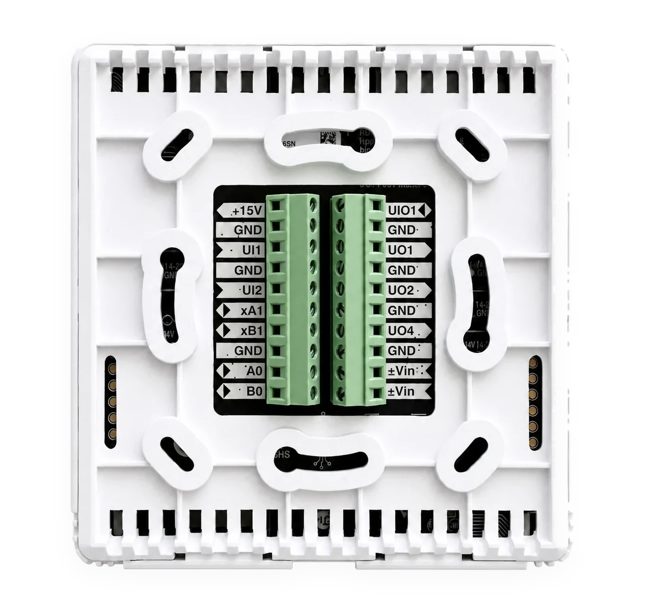
The Room Controller runs on 24 V and never sees mains voltage: 18–42 V DC or 24 V AC ±25 %, with 24 V recommended. (The Room Unit accepts 12–42 V DC or 24 V AC ±25 %, also 24 V recommended.) The MX-EXT5 runs on the same 24 V, 18–42 V DC or 24 V AC ±25 %. The MX-EXT5 connects to the wall device on terminals A1/B1 (7/6), while Modbus A/B (terminals 9/10) stays free for the building management system. Terminal labels follow the Room Controller datasheet. The MX-EXT5 ships in Mode 1 at Modbus address 8, 115200 baud, 8N1.
Output mapping: JOY Fancoil 5DO vs Alledio
Terminal names follow the labels printed on the Room Controller back plate (UI1, UI2, UO1, UO2, UO4, UIO1); the datasheet numbers some of them differently.
| Function | JOY Fancoil 5DO | Alledio Room Controller + MX-EXT5 |
|---|---|---|
| Fan speed 1 | Terminal 3 (3 A) | MX-EXT5 O1 (5 A) |
| Fan speed 2 | Terminal 2 (3 A) | MX-EXT5 O2 (5 A) |
| Fan speed 3 | Terminal 1 (3 A) | MX-EXT5 O3 (5 A) |
| Heating valve | Terminal 5 (500 mA) | MX-EXT5 O4 (5 A) |
| Cooling valve | Terminal 4 (500 mA) | MX-EXT5 O5 (5 A) |
| Inputs | DI1 (NTC10k or contact), DI2 (230 V) | Room Controller UI1, UI2 (NTC 10k, 0–10 V, 4–20 mA or digital) |
| BMS bus | Terminals 11/12 (Modbus A/B) + GND | Modbus A/B (terminals 9/10) |
| Power | L/N 85–260 V~ at the wall | 24 V AC/DC at the wall and at the MX |
The MX-EXT5 contacts are rated 5 A at 250 V AC resistive, with up to 16 A through the shared COM. All loads on that COM must be in one voltage band, and because the outputs aren't fused, you fit an MCB or fuse matched to the load, max. 5 A per Ox output, with max. 16 A on COM. In Mode 1 the firmware interlocks O1–O3 so that only one fan speed is ever closed. As the datasheet says, that interlock is an application function, not a safety function.
One wiring detail to note if you convert an existing JOY design: DI2 on the JOY 5DO accepts a 230 V signal, while the Alledio universal inputs accept up to 30 V and are not isolated. Use a volt-free contact (window, presence or key card) instead. A change-over sensor is no problem: an Alledio UI reads an NTC10k directly, just like JOY DI1. The Room Controller datasheet lists external temperature as NTC 10k, 0–10 V, 4–20 mA or Modbus.
Thermal valve actuators and PWM
If your fan coil uses thermal (wax) actuators, you may want to pulse them instead of plain on/off. Whether that works on the MX-EXT5 depends on the PWM period. The MX is a relay module, so its contacts have a limited number of switching cycles (100,000 electrical operations at 5 A, 250 V AC resistive). We suggest a shortest switching period of 1 mHz, which is one cycle every 1,000 seconds, or roughly 16 minutes. Thermal actuators take minutes to open anyway, so a slow period suits them. For fast modulation, use a 0–10 V actuator on a Room Controller universal output instead.
2-pipe fan coils
On a 2-pipe unit with one change-over valve, the setup stays the same: Room Controller + MX-EXT5, with O4 driving the valve. If you don't need the MX to switch any valve at all, for example because the valve is a 0–10 V actuator driven by a Room Controller output, the smaller MX-EXT3 covers the three fan speeds on its own. For more on this split, read our article on a 3-speed fan coil thermostat with a Modbus relay extender.


For the full wiring of a three-speed fan on Alledio, read our guide to the 3-speed AC fan coil thermostat with Modbus. If you are comparing relay-based thermostats in general, our article on the OEM Modbus relay thermostat lists what to check.
JOY Fancoil 5DO vs Alledio: specifications side by side
| Topic | JOY Fancoil 5DO (RS485 Modbus, 230 V) | Alledio Room Controller + MX-EXT5 |
|---|---|---|
| Devices | 1 wall unit | Wall unit + DIN-rail relay module (35 mm wide) |
| Supply | 85–260 V~ | Room Controller: 18–42 V DC or 24 V AC ±25 %, 24 V recommended. MX-EXT5: 18–42 V DC or 24 V AC ±25 % |
| Power consumption | max. 2.5 VA | Controller 0.3 W (50 % brightness); MX 0.2 W with contacts open, 1.5 W max. |
| Fan outputs | 3 NO, 240 V, max. 3 A | 3 NO on MX, 5 A at 250 V AC resistive, interlocked |
| Valve outputs | 2 NO, 240 V, max. 500 mA | 2 NO on MX, 5 A at 250 V AC resistive |
| Inputs | 2 (DI1 NTC10k/contact, DI2 230 V) | RC-TH-2: 2 universal inputs (UI1, UI2), incl. NTC 10k. RC-TH-3: UI1, UI2 + UIO1 |
| Display | 2.5" LCD, 240 × 160 px, touch-sensitive buttons | 3.5" capacitive touchscreen, 480 × 320 px, automatic brightness |
| Temperature accuracy | ±1 K (typ. at 21 °C) | ±0.5 °C average (0–60 °C) |
| Humidity | Optional, ±2 % (10–90 % rH); displayed and readable, not processed internally* | Standard, ±1.8 % (10–90 % at 25 °C) |
| CO₂ / VOC / presence | CO₂ optional (0–2000 ppm); displayed and readable, not processed internally* | CO₂ on THC versions (400–5000 ppm); VOC and presence optional |
| Bus options | Modbus RTU, BACnet MS/TP, KNX TP1, EnOcean, LoRaWAN, or standalone (per type) | Modbus RTU (client or server), Wi-Fi, Bluetooth LE, MQTT; BACnet as custom firmware |
| Modbus defaults | Address 32, 19200 baud, even parity | Controller: address and baud rate (9600–115200) set on the display; ¼ unit load, up to 128 devices per segment. MX-EXT5: address 8, 115200 baud, 8N1 |
| Configuration | Parameter menu on the device; uConfig (Windows) + microSD; or via the bus | Every installer parameter on the touchscreen; Use Case Simulator with installer PDF for partners |
| Firmware updates | Firmware files from Thermokon | Over-the-air via Wi-Fi |
| Protection | IP30 | Controller IP20; MX IP30 as installed in an enclosure |
| Size and mounting | 140 × 78 × 35 mm, EU flush box Ø 60 mm | 98 × 98 × 23 mm, EU flush box Ø 60 mm |
| Customisation | JOY Custom: 4 extra buttons, own logo lasered into the glass, MOQ 100 | Full OEM: logo, colours, UI layout and widgets, firmware, sensor mix, Modbus map; MOQ from 1,000 |
* Thermokon datasheet note: "Humidity and CO2 measured values are not processed internally. The values are displayed and can be read out by higher-level systems." Sources: Thermokon JOY FC 5DO RS485 Modbus datasheet (13.05.2026, A165), JOY brochure (11.24), Alledio Room Controller and Relay MX Extender product pages and datasheets on the Documents page, November 2026.
What matches and what differs
Where the JOY Fancoil 5DO is the stronger choice
- One device. Sensing, UI, control and switching are in a single wall unit. There's no second device to order, mount and address.
- Protocol choice. The same 5DO model exists for Modbus, BACnet MS/TP, KNX, EnOcean and LoRaWAN, or standalone. Alledio's standard firmware speaks Modbus RTU; BACnet is a custom job.
- IP30 at the wall. The JOY wall unit is rated IP30; the Alledio Room Controller is IP20.
- Small custom runs. JOY Custom with extra buttons and your logo starts at 100 pieces.
Where the Alledio Room Controller + MX-EXT5 is the stronger choice
- No mains at the wall. The room cable carries 24 V and RS485 only. Fan and valve wiring stays short, inside the fan-coil enclosure.
- More headroom on the outputs. 5 A per contact for the fan and the valves, against 3 A and 500 mA.
- Better room data. ±0.5 °C accuracy, humidity on every unit, and CO₂, VOC and presence sensing as options.
- Quieter, cooler wall unit. Relay clicks and switching heat stay on the DIN rail, away from the room and the sensors.
- Same wall box. The Room Controller also fits a standard EU Ø 60 mm flush box, so a retrofit doesn't need new boxes.
- Connectivity and updates. Wi-Fi, MQTT and over-the-air firmware updates on top of Modbus.
- Modular service. If a relay ever needs replacing, you swap the DIN-rail module and leave the wall unit alone.
What about the 24 V JOY Fancoil 5DO?
Thermokon also offers a 24 V version of the JOY Fancoil 5DO, so mains at the wall isn't the whole story. Its datasheet rates the five contacts at 24 V, max. 3 A. That suits 24 V fan coil loads. Most fan coils with three-speed AC fans and 230 V valve actuators would then need additional relays. The Alledio setup builds those relays in as the MX-EXT5, controlled over Modbus.
Commissioning and integration
With JOY, Modbus settings can be changed in the device's parameter menu (address, baud rate and parity, accessible for the first 60 minutes after power-up). The full configuration is created in Thermokon's uConfig software, which needs Microsoft Windows, and transferred on a microSD card, or set live over the bus.
The Alledio Room Controller is configured on its own touchscreen, without an app, dongle or laptop. OEM partners also get the Alledio Use Case Simulator in the Partner Hub. You pick the application, here a 4-pipe fan coil with a 3-speed AC fan and two on/off valves on the MX, and the simulator shows the device code, the terminal assignment on the back plate and a PDF for the installer.
On the bus side, both are Modbus RTU devices on RS485. If you mix them on one segment, plan the addresses and bus settings: JOY ships at address 32, 19200 baud, even parity, and the MX-EXT5 at address 8, 115200 baud, 8N1. On the Room Controller you set the address and baud rate on the display. The Alledio transceiver draws a quarter unit load, so up to 128 controllers can share a segment electrically, according to the FAQ on the Alledio Room Controller page. That 128 is the electrical limit, not a promise for every installation: cable length, baud rate, termination and polling load all decide how many devices a real bus carries. Terminate both ends and use proper twisted pair. Before you hand over, our guide on how to test a Modbus RTU device shows a quick bench check.
Design, simplicity and the flexibility of the Alledio OEM solution
Design
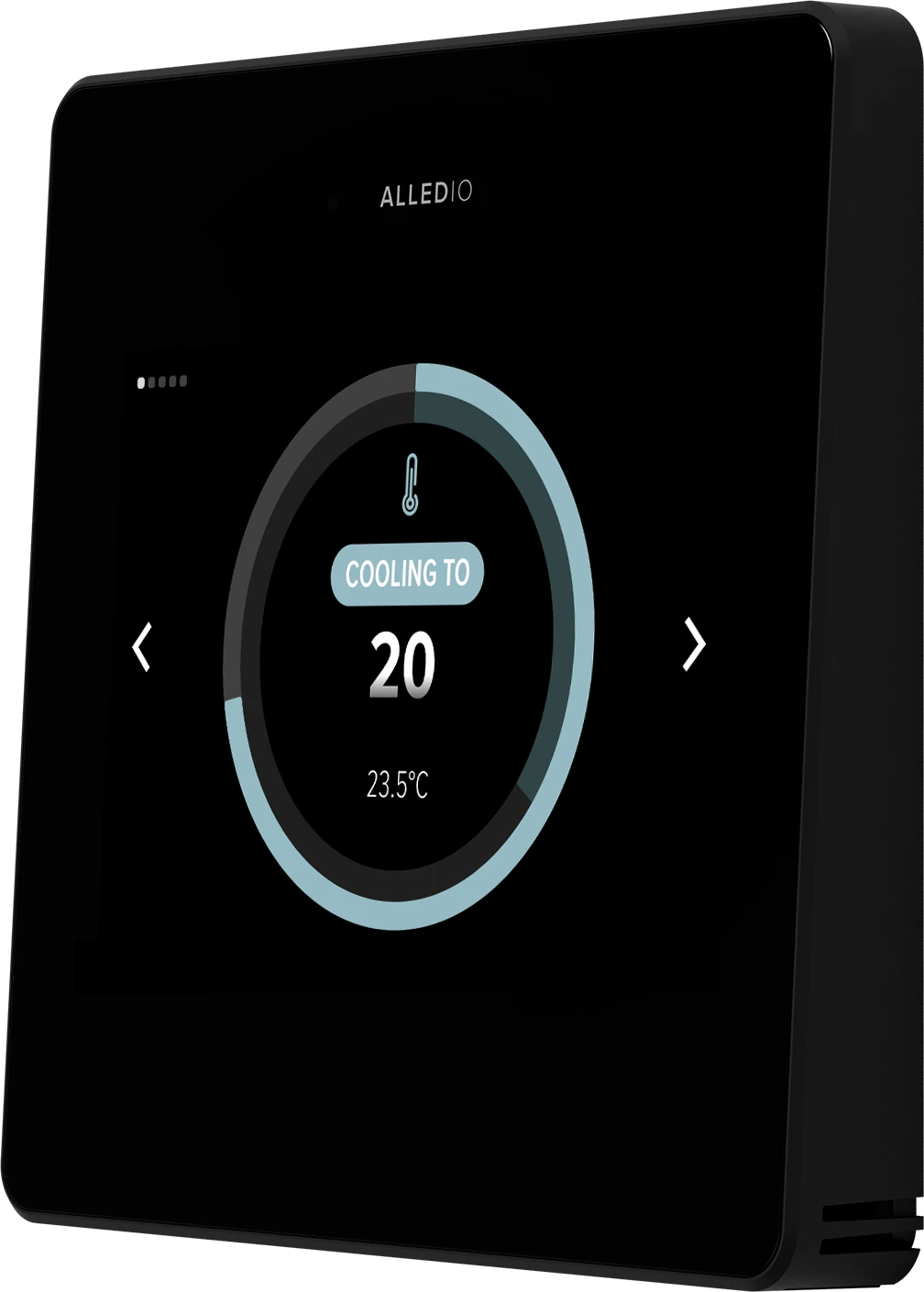
Both devices sit behind glass, and both look at home in an office or a hotel room. JOY combines a 2.5" LCD with touch-sensitive buttons in a slim 140 × 78 mm frame. The Alledio Room Controller is a square 98 × 98 × 23 mm unit whose whole front is a 3.5" capacitive touchscreen with automatic brightness. It comes in white, black and silver as standard, and custom colours are possible for OEM orders.
Simplicity
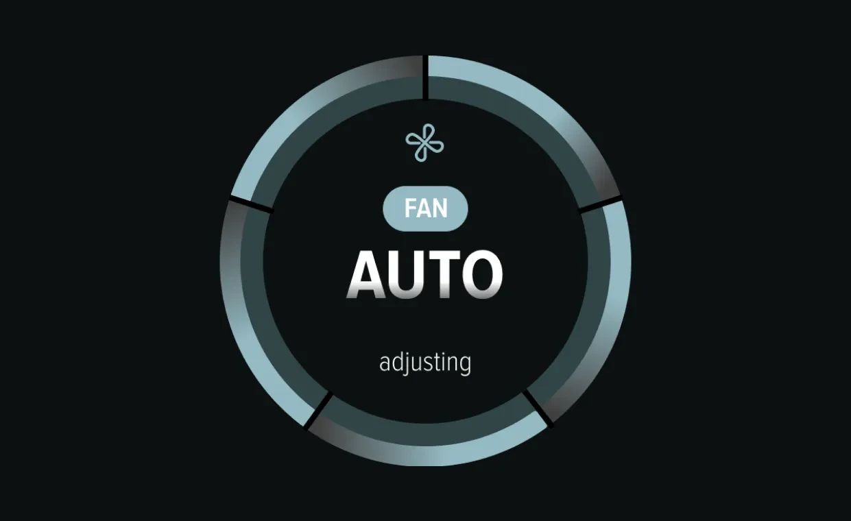
On site, the Alledio approach keeps the wall simple: one 24 V supply and one twisted pair. The MX-EXT5 mounts on a DIN rail inside the fan-coil enclosure, so the 230 V load wiring stays short and at the unit. As a fan coil manufacturer you can also mount and pre-wire the MX-EXT5 in the unit at the factory, which is always an option. The installer then only connects 24 V and the Modbus pair to the wall. Day to day, the occupant sees fan speed (1, 2, 3 or auto), setpoint, schedules and notifications on one touchscreen.
OEM flexibility and UI customisation
This is where the two products differ most. JOY Custom adds four configurable buttons and a lasered logo to a finished Thermokon product. The Alledio OEM programme lets you turn the Room Controller into your own product:
- Branding: your logo on the glass and on the welcome screen, and the UI colours matched to your corporate palette.
- Layout and screens: decide which screens exist and what each one shows, and add new widgets that fit the rest of the UI.
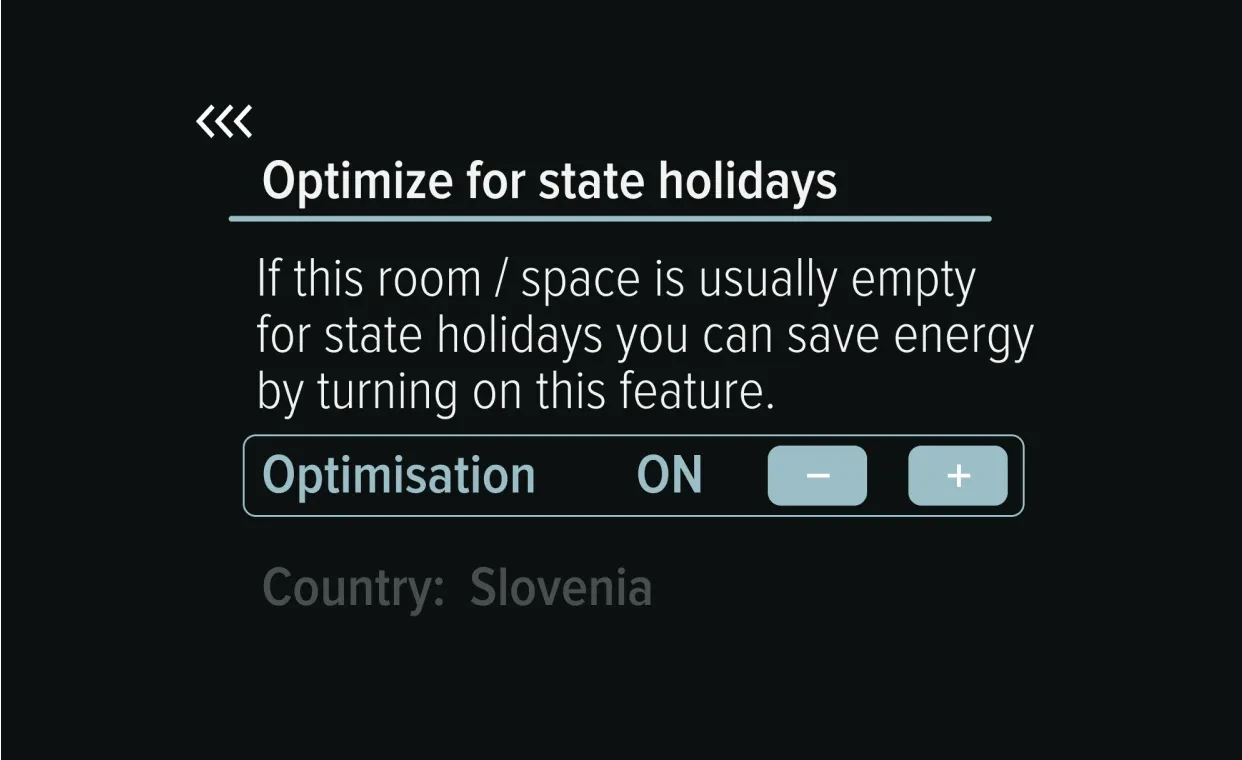
- Per-application UI: a hotel guest room might show only setpoint and fan speed. An office might add CO₂ and a schedule. A residential unit might add holiday and absence modes. One hardware platform, different interfaces.
- Firmware: application features, multi-language support, and a Modbus register map matched to your existing product line, so your integrators can reuse their templates.
- Hardware: sensor mix (CO₂, VOC, presence), I/O version and case colour.
The trade-off is volume. Alledio is supplied only to companies that build their own HVAC equipment, with an MOQ from 1,000 pieces and a lead time of 8–12 weeks after design and firmware sign-off. Samples with demo firmware are available.
Who should choose which?
Choose the JOY Fancoil 5DO if you are fitting out a project with a catalogue controller, you need BACnet, KNX, EnOcean or LoRaWAN, you want one device at the wall, or you need a custom version in small quantities.
Choose the Alledio Room Controller + MX-EXT5 if you manufacture fan coils or other HVAC units and want a controller under your own brand, you want only 24 V at the wall with the relays inside the unit, and you value a touchscreen UI, better room sensing and firmware you can shape around your product.
Not sure which Alledio version fits your fan coil? Our guide to the 3-speed FCU OEM thermostat covers the common configurations, and partners can model their own in the Use Case Simulator after signing in to the Alledio Partner Hub.
JOY Fancoil 5DO vs Alledio FAQ
What is the Alledio equivalent of the Thermokon JOY Fancoil 5DO?
The Alledio Room Controller combined with the MX-EXT5 Modbus relay extender in Mode 1, sold together as the Alledio Thermostat. The MX-EXT5 switches the three fan speeds on O1–O3 and the heating and cooling valves on O4 and O5. RC-TH-2 matches the JOY's two inputs; the Room Unit RU-TH-0 also drives the MX-EXT5 if you need no wired inputs.
Can the Alledio Room Controller switch a 230 V fan directly?
No. The Room Controller runs on 18–42 V DC or 24 V AC ±25 %, and its universal outputs are 0–10 V (max. 10 mA), 4–20 mA or open-collector digital. 230 V fan speeds and valves are switched by the MX-EXT5 at the fan coil, at up to 5 A per contact.
Can the MX-EXT5 drive thermal valve actuators with PWM?
It depends on the PWM period. The MX-EXT5 is relay based, so its contacts allow a limited number of switching cycles. We suggest a shortest switching period of 1 mHz, about one cycle every 16 minutes. For fast modulation, use a 0–10 V actuator on a Room Controller output.
Does the Alledio setup work on 2-pipe fan coils?
Yes. On a 2-pipe unit the change-over valve goes on O4 of the MX-EXT5, and the fan speeds stay on O1–O3.
Can the MX-EXT5 be mounted in the fan coil at the factory?
Yes. Fan coil manufacturers can always mount and pre-wire the MX-EXT5 on a DIN rail inside the unit at the factory, so only 24 V and one Modbus pair run to the wall.
Does the Alledio Room Controller fit a standard wall box?
Yes. It fits a standard EU flush box (Ø 60 mm), the same box type the JOY Fancoil 5DO uses.
Is there a 24 V version of the JOY Fancoil 5DO?
Yes. Thermokon lists a 24 V JOY Fancoil 5DO whose five contacts are rated 24 V, max. 3 A, according to its datasheet.
Can installers buy the Alledio Room Controller?
No. Alledio is supplied only to manufacturers that bundle it with their own HVAC equipment, with an MOQ from 1,000 pieces.
Conclusion
The JOY Fancoil 5DO and the Alledio Room Controller + MX-EXT5 solve the same fan coil job: three fan speeds and two valves. JOY does it in one well-proven device with a wide choice of protocols. Alledio keeps mains out of the wall, puts 5 A relays next to the loads, and gives a manufacturer a touchscreen controller it can brand and adapt. If you build fan coils and want the controller to be part of your product, see the Alledio Thermostat, then talk to us about your fan coil range.
Related reading
JOY, EasySens and Thermokon are trademarks of Thermokon Sensortechnik GmbH. Alledio is not affiliated with Thermokon. Specifications are as published on the dates cited and may change. Always check the current manufacturer datasheets for your project.