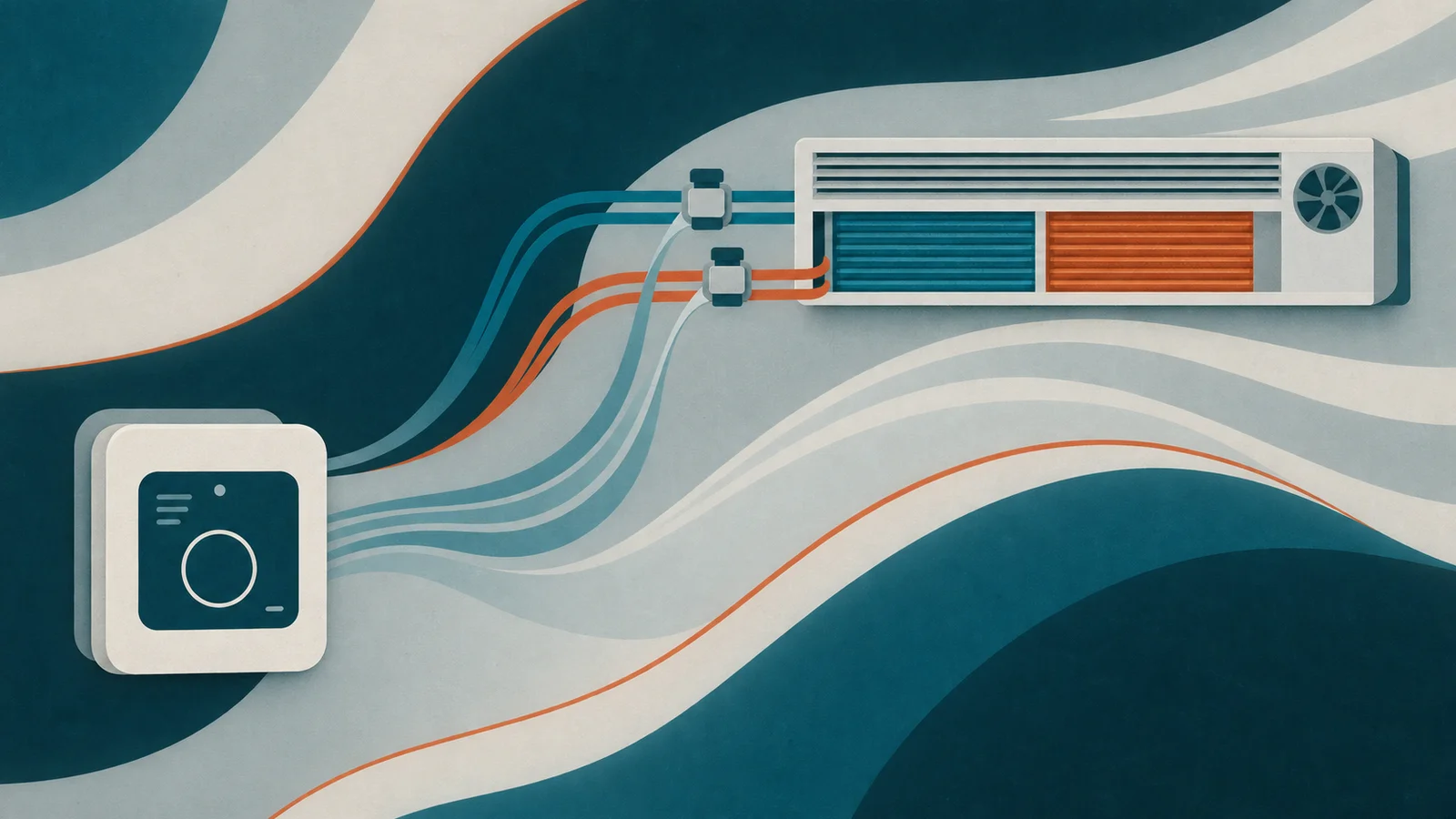
Two-pipe FCU platforms that still mix a wall display with a separate valve board lose months in every RFQ. A 2-pipe fan coil room controller with 0-10V valve puts glass, sensors, and the analogue valve (plus EC fan path) on one flush Room Controller - changeover and plant safeties stay on the host you certify.
OEM2-Pipe FCU0-10 VModbusRoom ControllerHVAC
Who specifies 2-pipe + 0-10 V on a Room Controller
This article is for HVAC OEM product and R&D teams whose fan-coil line uses a single water circuit with changeover and an analogue valve - not for installers. If your motor is three-speed 230 VAC relays, use the Thermostat family instead.
Alledio is OEM-only: designed in Slovenia, manufactured in the EU. MOQ 1,000 negotiable; 500 possible when several Room Unit or Room Controller versions combined exceed 1,000. Samples use demo or test firmware under NDA via /oem.
Two-pipe is not four-pipe, and it is not a relay thermostat job. Four-pipe simultaneous heat/cool with two valve paths is covered in the 4-pipe guide. Relay FCU walls are covered in 3-speed FCU OEM thermostat and OEM Modbus relay thermostat. Here the focus is 2-pipe + 0-10 V valve on RC.
Seasonal hotels and cost-optimised office FCUs still dominate two-pipe installs. The RFQ must say how changeover is decided and which analogue lines drive valve and fan - otherwise commissioning invents a second controller in the ceiling.
Write the expected valve stroke time and fan ramp into the application note so lab tests match the field. That is how you avoid a glass that looks finished while the actuator still hunts on a wrong UO scale.
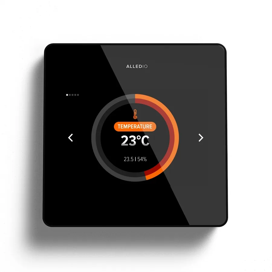
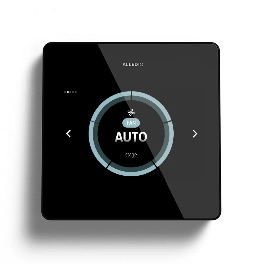
2-pipe fan coil room controller with 0-10V valve - mapping the UO
On a two-pipe coil the usual analogue citizen is one valve position plus an EC fan command. Both sit in the Room Controller UO class (0-10 V), not on mains fan relays. Write changeover ownership - water temperature sensor, host bit, or glass request - into the same ICD as the pin map.
Published maximum mix remains 2× UI, 3× UO, and 1× UIO across TH / TH1 / TH2 / TH3. Order the version that matches the terminals you need. Empty pins are a commercial choice, not free field creativity.
Spare UI channels often take a pipe sensor, window contact, or occupancy input. Document those as named options so the lab sample mirrors the production pinout.
Pin-map discipline beats terminal folklore. Prefer UO/UI class language in the RFQ when the exact board revision is still open, then lock terminal labels once the TH / TH1 / TH2 / TH3 version is ordered. Commons, cable class, and RS-485 termination belong next to the analogue lines in the same pack - not in a separate email that never reaches the panel shop. Tie every Modbus register that writes a UO to the same named channel so firmware NRE does not reinvent the wall map.
If the BMS already owns changeover, keep the glass in request mode and publish which Modbus bits are advisory only. That contract stops occupants from fighting a central seasonal mode.
Changeover ownership in the ICD
Two-pipe does not mean simultaneous heating and cooling. Keep that topology on the 4-pipe article. Here the RFQ must name how the system decides heat vs cool and how the glass presents mode without contradicting the host sequence.
Three ownership patterns show up in OEM RFQs. Host-owned changeover: the BMS or plant controller writes a heat/cool bit and the glass only requests; advisory Modbus coils must be labelled as such. Sensor-owned changeover: a pipe or return-water sensor on a spare UI drives local logic, with a clear hysteresis and a fail-safe when the sensor is open. Glass-request changeover: the occupant or schedule asks for a mode that the host may reject - publish the reject path so the UI does not look broken. Write the chosen pattern into the ICD cover sheet before pin numbering.
Valve and EC fan both land in the UO class. A typical 2-pipe map puts the valve position on one UO and the EC fan speed on another, leaving the third UO for enable, damper, or a second analogue when the coil needs it. Do not assign mains fan relays here. Name each UO with engineering units (0-10 V = 0-100 % stroke, or your actuator curve) so lab benches and field panels share one scale definition.
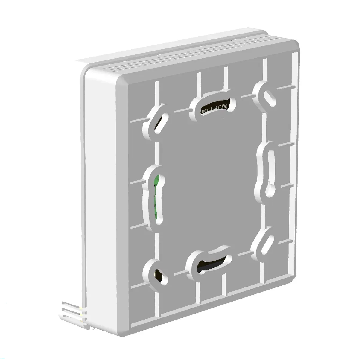
Put cable class, commons, and termination next to the valve and fan UO lines. Field teams waste days when the panel looks finished but the analogue class was never documented. Tie Modbus registers to the same pack.
When the motor is still 3-speed AC
If the coil still expects speed 1/2/3 relays at 230 VAC, stop this RFQ and open the Thermostat path on Alledio OEM Thermostat. Do not invent 3-speed 230 VAC relays on the Room Controller. RC fan is the analogue / EC path.
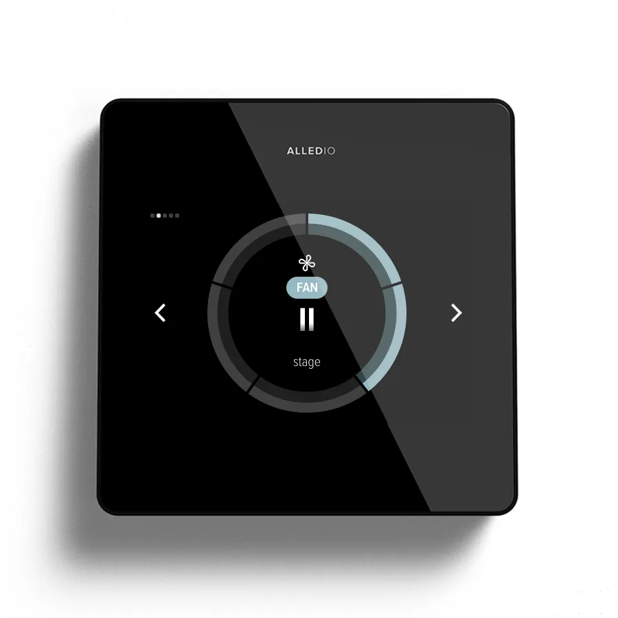
2-pipe vs 4-pipe and relay thermostats
For the full I/O platform, see OEM room controller with universal I/O. Simultaneous heat/cool with two valve paths is covered in 4-pipe fan coil room controller with 0-10V. Relay FCU walls belong on 3-speed FCU OEM thermostat and Alledio OEM Thermostat (Modbus relay). This guide covers 2-pipe + 0-10 V valve on RC only.
Use a decision line in the RFQ. One water circuit with changeover and analogue valve/fan → this Room Controller path. Two independent valve paths for simultaneous heat and cool → the 4-pipe guide. Three-speed 230 VAC fan relays and heat/cool contactors → Thermostat family. Mixing those envelopes in one purchase order is how projects inherit adapters, wrong power classes, and a glass that cannot drive the motor it was sold against.
White-label programmes still need the same split: brand the correct family. A hotel chain that runs seasonal two-pipe EC coils should not inherit a relay thermostat UI just because the lobby brochure looks similar. Align the wall SKU with the coil electrical class before logo and colour work begin - that is cheaper than a mid-project hardware swap.
Power on RC is 18-42 V DC (24 V recommended) or 24 VAC ±25%. Never 230 VAC. Bus default is Modbus RTU on RS-485. No native BACnet or KNX catalogue SKU.
Display-only programmes without wall I/O belong on the Room Unit. Mixing RU, RC, and Thermostat envelopes in one PO is how commissioning invents adapters.
Glass, mechanics, OEM
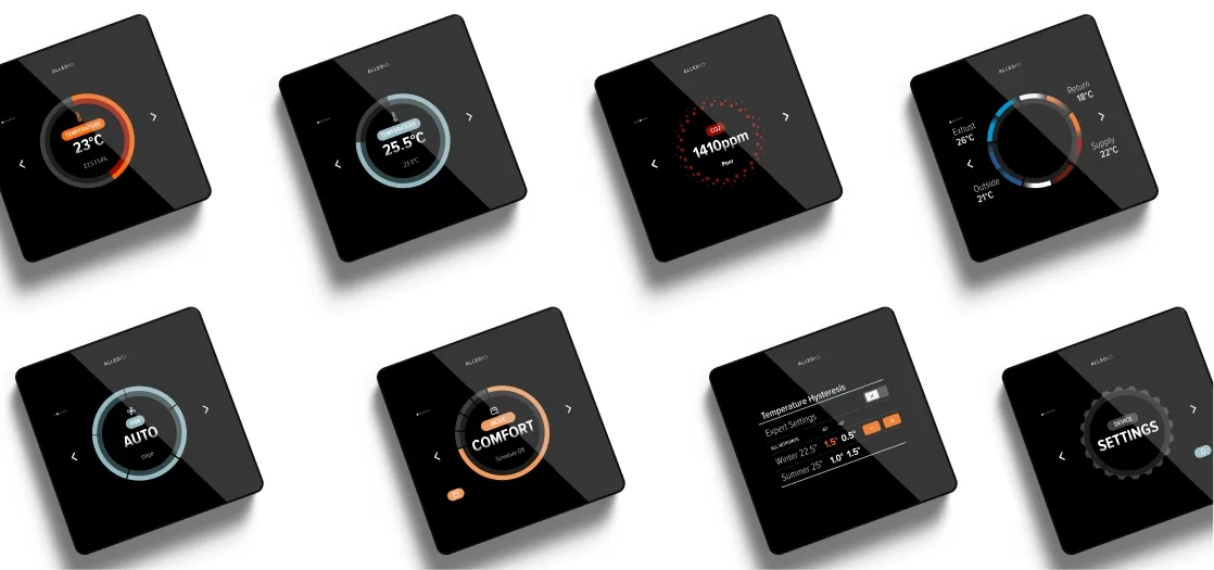
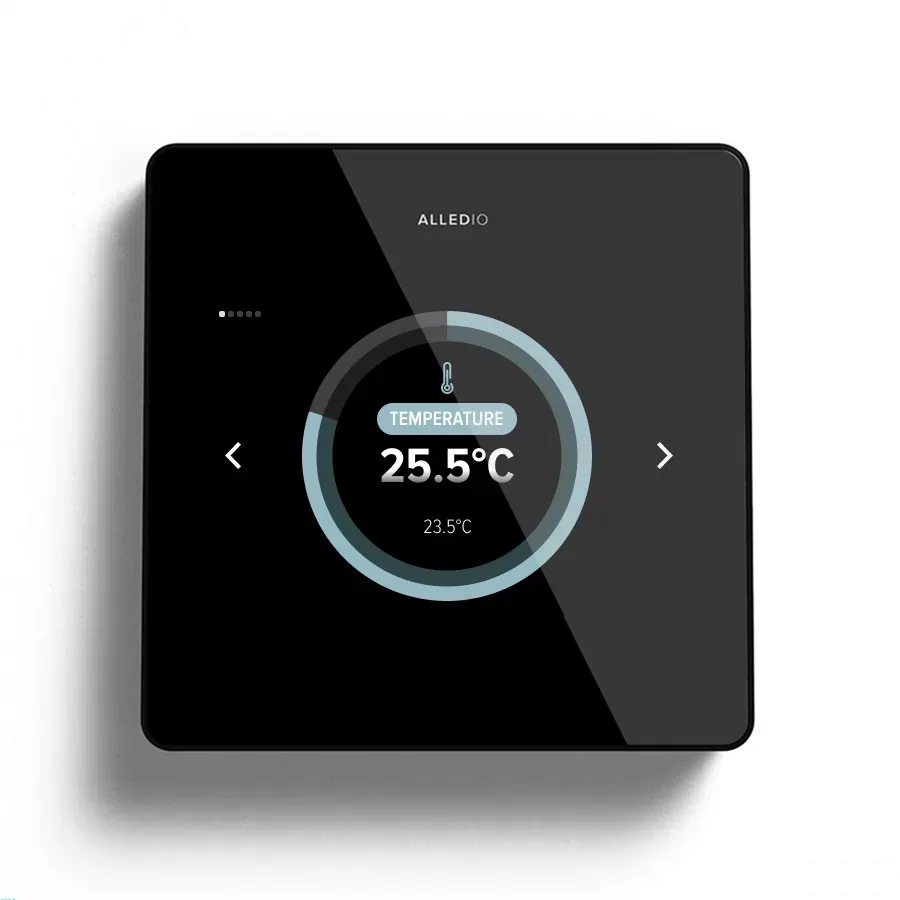
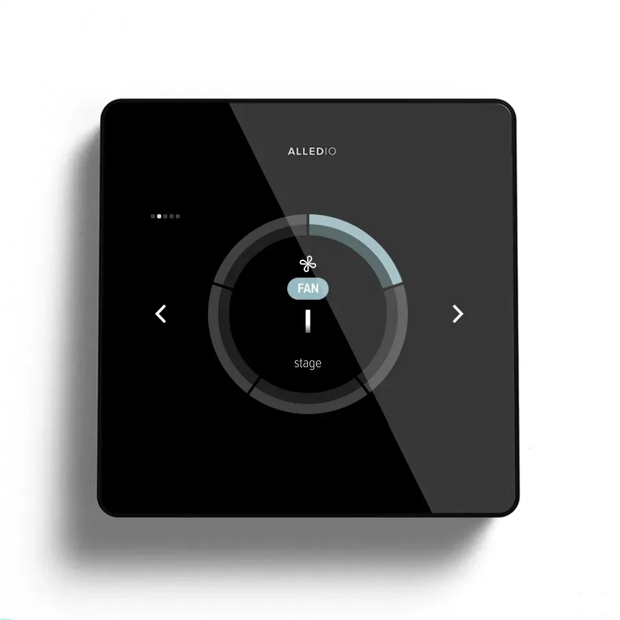
Mechanics: 98 × 98 × 23 mm, 150 g, IP20. Display: 3.5″ 480×320 capacitive. Same visual family as Room Unit; thicker than the 14 mm thermostat so terminals fit.
OEM customisation covers logo, UI, widgets, hardware options, firmware NRE. Samples first with demo/test firmware; production firmware quoted against your map. See also 3.5 inch touch panel, MCE Milano 2026, and about.
Bring a one-page application note to the sample request: changeover owner, valve UO curve, EC fan UO curve, optional UI list, Modbus address plan, and power class (24 V DC preferred). That pack lets the lab exercise the same behaviours the field will see, instead of a generic demo that never touches your 2-pipe sequence. Production firmware is quoted against that map; do not treat the sample image as a frozen SKU.
Commercial gate remains OEM-only. MOQ 1,000 negotiable; 500 possible when several Room Unit or Room Controller versions combined exceed 1,000. No installer webshop. Plant safeties, frost protection, and certified sequences stay on the host you certify - the wall unit executes the analogue and glass contract you publish.
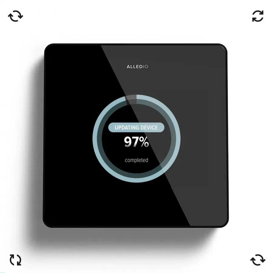
Product proof
Published proof for 2-pipe analogue FCU is 0-10 V valve + EC fan on Room Controller UO, Modbus on copper, EU OEM programme - not a retail thermostat and not a four-pipe simultaneous map.
| Topic | Published spec |
|---|---|
| Display | 3.5″ LCD, 480 × 320, capacitive touch, auto brightness |
| Sensors (standard) | Temperature and humidity |
| Sensors (optional) | VOC, CO2 (400-5000 ppm), pressure, presence |
| Universal I/O (max) | 2× UI, 3× UO, 1× UIO (TH / TH1 / TH2 / TH3) |
| I/O classes | Analogue 0-10 V / 4-20 mA; digital open-collector / 0-30 V input |
| Fan path on RC | Analogue 0-10 V / EC on UO - not 3-speed 230 VAC relays |
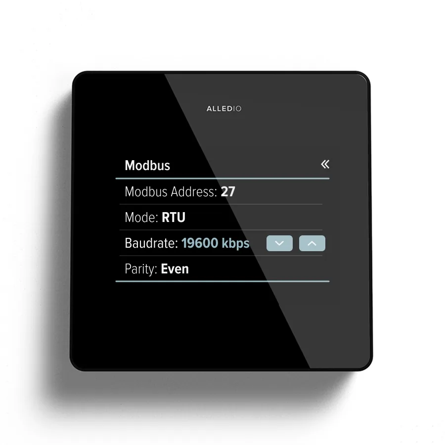
| Bus | RS-485 Modbus RTU (slave default; master on request), 9600-115200 |
| Radio / API | Wi-Fi 2.4 GHz with OTA; MQTT/REST for authorised partners; BLE 5 ready |
| Power | 18-42 V DC (24 V recommended) or 24 VAC ±25%; never 230 VAC on RC |
| Mechanics | 98 × 98 × 23 mm, 150 g, IP20 |
| Origin | Designed Slovenia, manufactured EU |
| Commercial | OEM-only; MOQ 1,000 (negotiable; 500 if several RU/RC versions combined exceed 1,000); samples with demo/test firmware |
Not a catalogue claim here: native BACnet; KNX SKU; webshop; 230 VAC relays; simultaneous four-pipe on this page. Confirm the datasheet. Deeper work: hardware and software development. Compliance starts from RED and RoHS.
FAQ
Is this a thermostat with a 0-10 V valve?
No. It is a Room Controller. Thermostat SKUs are 230 VAC relay-centric. Valve and EC fan analogues sit on RC universal outputs.
How is this different from the 4-pipe post?
2-pipe is one water circuit with changeover and typically one valve path. 4-pipe handles simultaneous heat and cool with separate valve paths. Keep the RFQs separate.
Can we get samples?
Yes. Samples include demo or test firmware under NDA so your lab can validate the valve UO, fan analogue, Modbus, and glass before production NRE.
What is the MOQ?
MOQ starts at 1,000 and is negotiable. 500 is possible when several Room Unit or Room Controller versions combined exceed 1,000.
Can we run 3-speed AC fan relays on this controller?
No. Published RC fan path is analogue 0-10 V / EC. Use the Thermostat family for 230 VAC 1/2/3/Auto/off relays.
Installer webshop?
No. OEM channel only.
What belongs in the ICD for a 2-pipe analogue RFQ?
Changeover ownership, named UO channels for valve and EC fan with scales, spare UI options, Modbus write map for those channels, power class, and cable/commons notes. Without that pack, commissioning invents a second controller.
What to do next
Start on Alledio OEM Room Controller, then open OEM for logo, I/O version, NRE, and samples. Bring the 2-pipe changeover note, valve/fan UO map, Modbus draft, and MOQ. That is the shortest path from an RFQ sentence to a 2-pipe 0-10 V wall controller under your brand.