
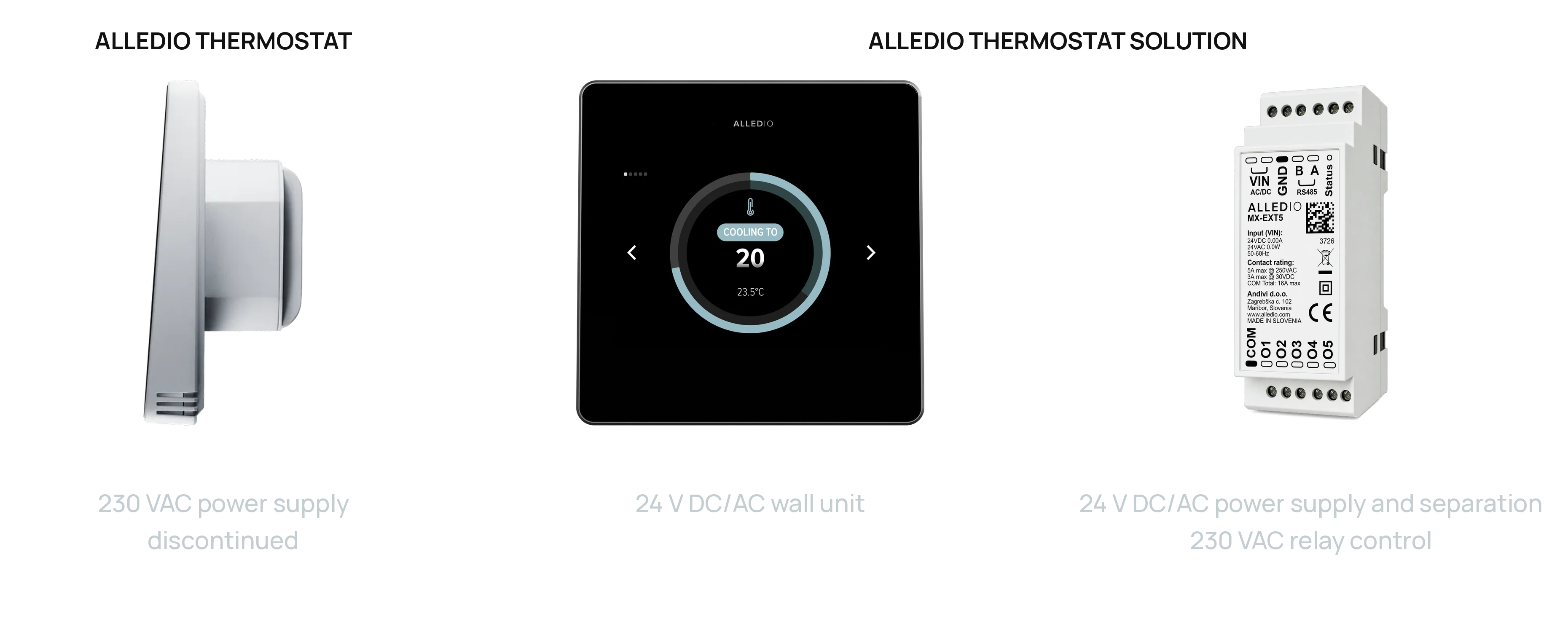
A 3-speed fan coil needs three fan relays, often one or two valve relays, and a thermostat that the building management system can read. The Alledio answer is a fan coil thermostat with a Modbus relay extender sold as one set: the 24 V Room Controller on the wall and the Relay MX Extender on the DIN rail, joined by one RS485 Modbus RTU twisted pair. The same set covers a 4-pipe fan coil with separate heating and cooling valves and a 2-pipe fan coil with a changeover valve.
OEMModbusRelay MXFCU3-Speed24 V
Coming from the 230 VAC Alledio thermostat? That model is discontinued and this set replaces it. Read what changed and how existing installations are supported.
Who this is for
Read this if you build fan coil units, air handlers or DX equipment, or you make BMS devices, and you want a white-label wall controller that switches a 3-speed AC fan and on/off valves. Alledio sells to OEMs only. Installers and integrators buy through your channel, under your brand.
The set is one Alledio Room Controller and one Relay MX Extender per room, both on one 24 V supply and one Modbus line. It ships as a matched, pre-configured set, ready for your branding.
Why the relays sit on the DIN rail
The old thermostat switched 230 VAC inside the wall unit. Splitting control and power makes the installation safer and the readings more accurate.
- No 230 VAC at the wall. The room cable carries 24 V and RS485 only. Mains wiring stays in the cabinet, where the loads are.
- Better measurement. Switching heat stays out of the wall unit, away from the temperature and humidity sensors.
- Silent room. Relay clicks happen on the DIN rail, not next to the bed or the desk.
- One wall unit for every system. The same Room Controller works with relays, with 0-10 V outputs, or Modbus only. You pick the relay module per project.
- Easier service. If a relay ever needs replacing, you swap the DIN-rail module, not the wall unit.
- Short load wiring. Only 24 V and Modbus run to the wall. Fan and valve wires stay short at the fan coil.
How the 3-speed fan and valves are switched
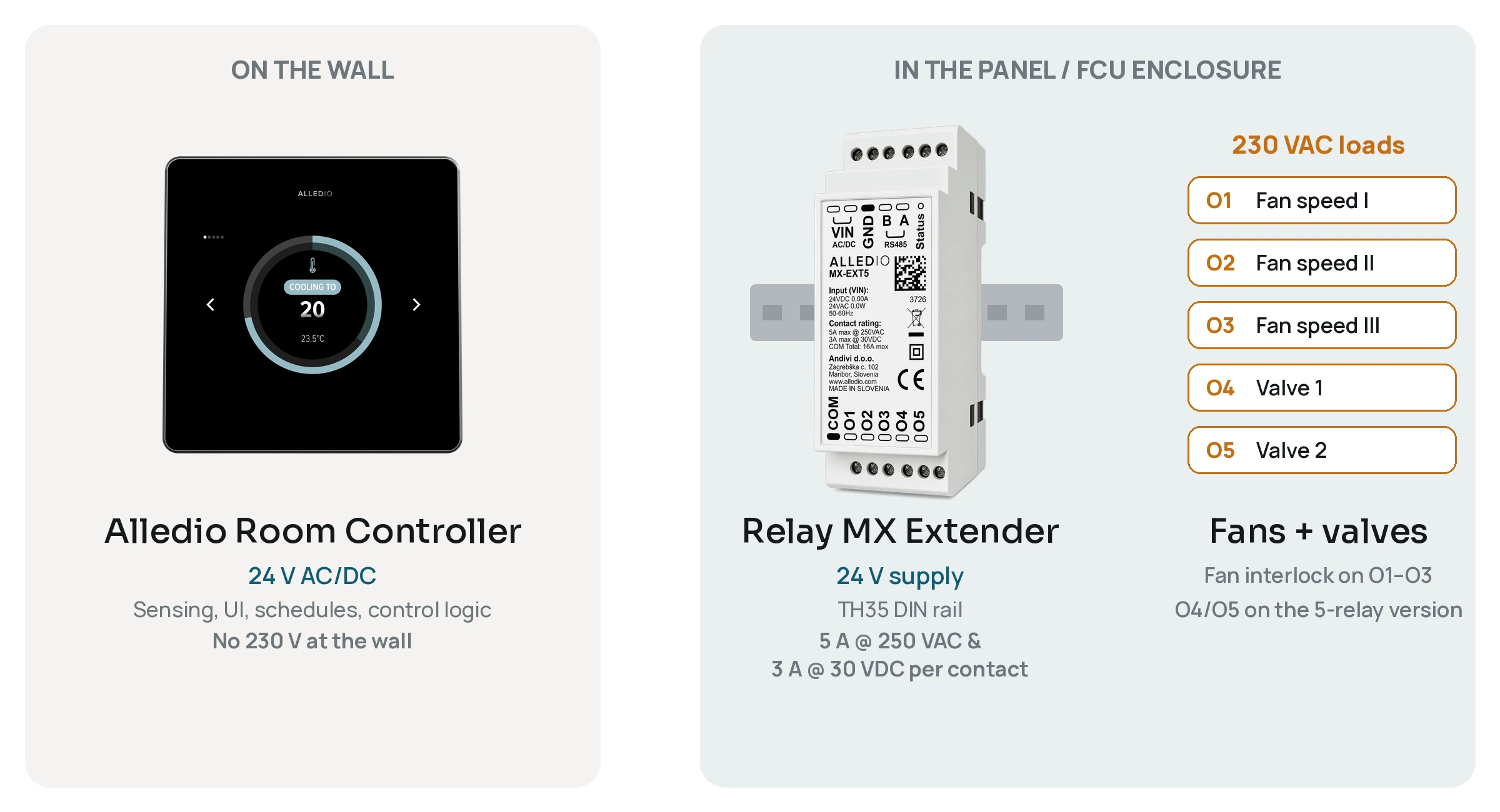
The Relay MX Extender ships in fan coil mode (Mode 1), so the Room Controller commands it over Modbus out of the box:
- O1, O2, O3: fan speed 1, 2 and 3, on both relay versions.
- O4: valve 1, for example heating (5-relay version only).
- O5: valve 2, for example cooling (5-relay version only).
A firmware interlock lets only one fan speed relay close at a time. It is an application function, not a safety function. The user sees speed 1, 2, 3, auto and off on the wall unit.
Need a modulating valve instead of an on/off valve? Use a 0-10 V output on the Room Controller (versions TH1 to TH3) next to the relays. Two other modes are set over Modbus: independent relays, and curtain control.
2-pipe or 4-pipe: which set to order
Start from the loads you have to switch:
- 4-pipe fan coil, 3-speed fan plus heating and cooling valves: Room Controller + Relay MX Extender, 5 relays (MX-EXT5).
- 2-pipe fan coil, 3-speed fan plus one changeover valve: Room Controller + Relay MX Extender, 5 relays, with O4 for the valve.
- 3-speed fan only, or fan plus a modulating 0-10 V valve: Room Controller (TH1 to TH3 for 0-10 V) + Relay MX Extender, 3 relays (MX-EXT3).
- No 230 VAC loads (0-10 V actuators, Modbus-only units): the Room Controller alone.
The Room Controller on the wall
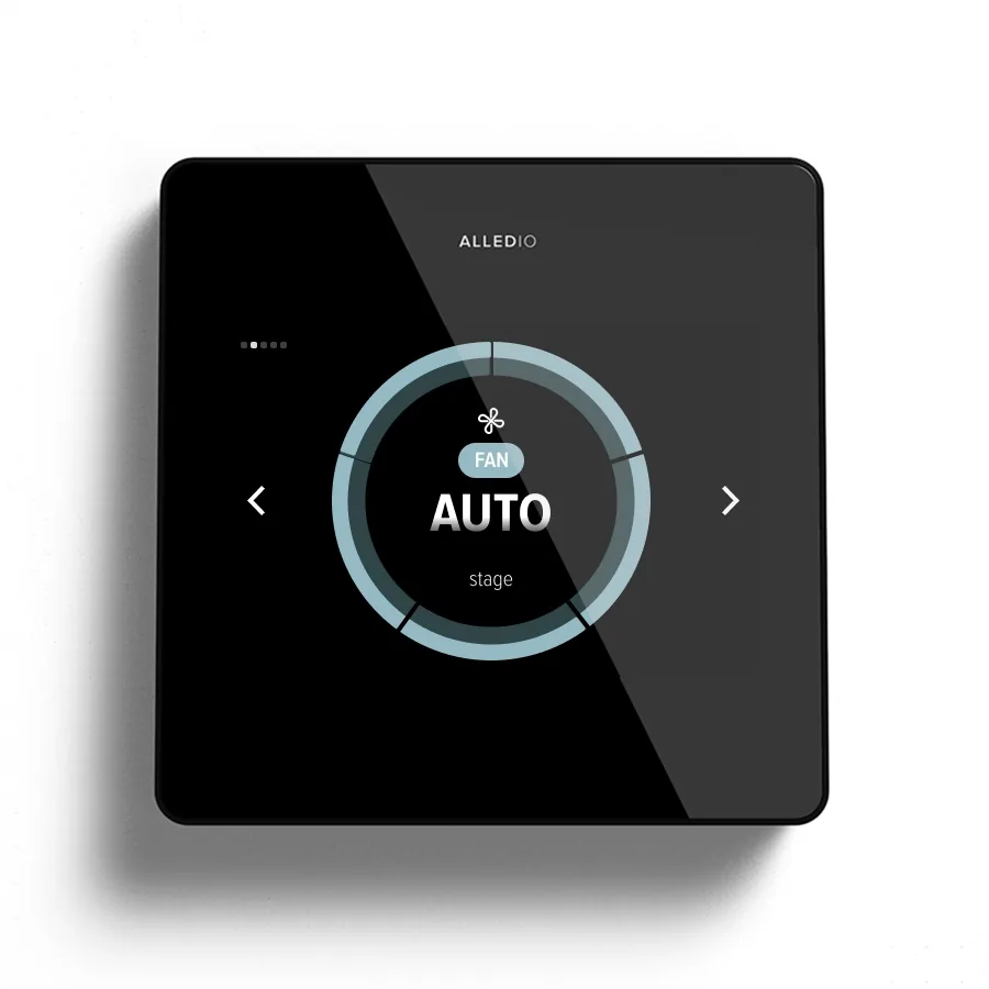
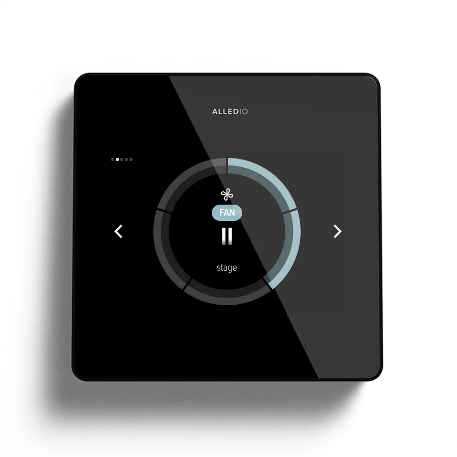
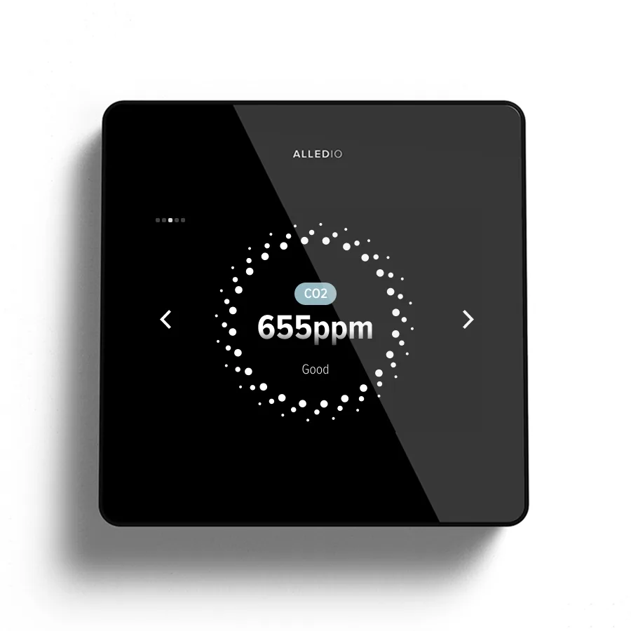
The Room Controller measures temperature and humidity as standard, with CO2, VOC and presence as options. It shows a 3.5-inch, 480 × 320 capacitive touch display and runs the control logic. It is powered by 24 V: 18–42 V DC or 24 V AC ±25 %. There are no relays in the wall unit.
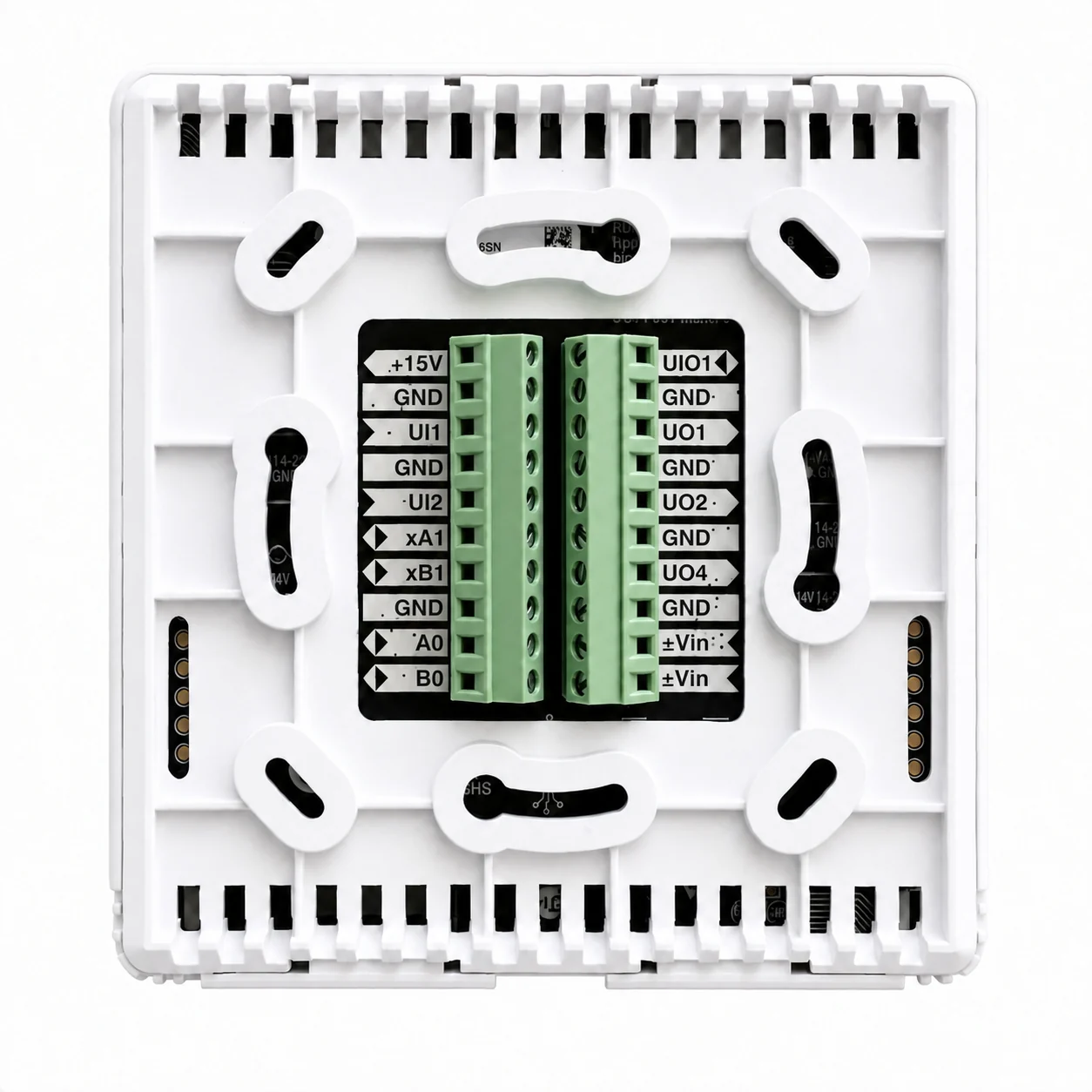
It comes in four I/O versions. TH has no I/O. TH1 has 1 universal output and 1 universal input. TH2 has 2 of each. TH3 has 3 outputs, 2 inputs and 1 input or output (UO1, UO2, UO4, UI1, UI2 and UIO1). Outputs work as 0-10 V (10 mA), 4-20 mA sink or open-collector digital outputs (1 A). Inputs take 0-10 V, 4-20 mA or digital signals.
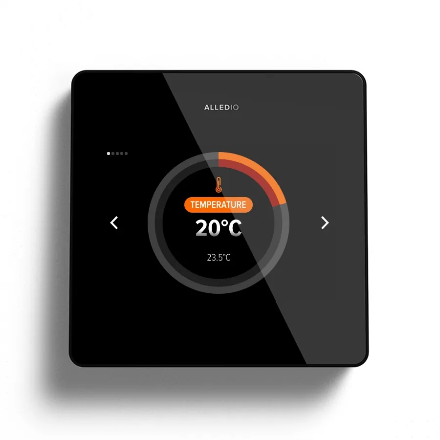
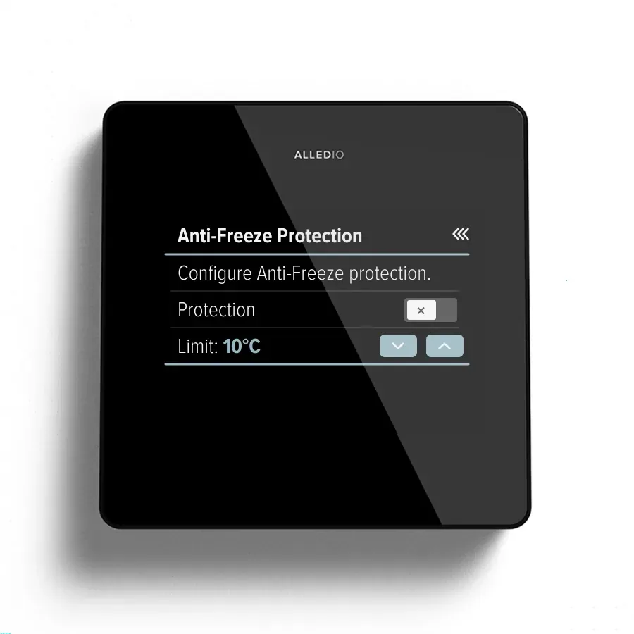
Setup happens on the display, without an app. Wi-Fi (2.4 GHz) is used for over-the-air updates, and Bluetooth 5 LE is ready. The housing is ABS with glass, IP20, 98 × 98 × 23 mm and 150 g, in white, black or silver.
The Relay MX Extender in the panel
Relay MX is a DIN-rail relay module made by Andivi in Maribor, Slovenia. MX-EXT5 has five normally-open contacts (O1–O5) and MX-EXT3 has three, both with a shared COM. Each contact switches 5 A at 250 V AC or 3 A at 30 V DC (resistive), with up to 16 A through COM.
It runs on 24 V AC ±25 % or 18–42 V DC and draws 0.2 W with the contacts open, 1.5 W max. It mounts on a TH35 DIN rail in a closed cabinet or fan coil enclosure (IP30 as installed) and measures 35 × 89.6 × 31.25 mm, about 100 g.

A few wiring rules from the datasheet:
- Loads connect between each output and COM. All outputs on one COM must be in one voltage band, so do not mix 230 V AC and extra-low voltage.
- Outputs and COM are not fused. Fit an MCB or fuse matched to the load, max. 5 A per output.
- The contacts provide micro-disconnection only and are not a disconnecting safety device.
Modbus, commissioning and the BMS
Both devices speak Modbus RTU over RS-485. The Relay MX Extender ships at address 8, 115200 baud, 8N1. The address is set over Modbus in the range 1–247, and 120 Ω bus termination can be switched on over Modbus too. Because factory-fresh modules share address 8, you commission them one at a time by factory serial number.
The Room Controller supports 9600 to 115200 baud with none, even or odd parity, and software bus termination. It works as a Modbus server as standard, or as a client on request. It integrates with any BMS that supports Modbus, for example Siemens Desigo, Schneider Electric EcoStruxure or Tridium Niagara. BACnet and proprietary protocols can be implemented on request.
One Room Controller can also command several Relay MX Extenders on the same Modbus line, so a group of fan coils runs on one setpoint. Check the load per contact (5 A) and per COM (16 A) for each fan coil. For the I/O side of the wall unit, see how the Room Controller universal I/O works.
White label and what to put in the RFQ
UI, firmware, colours, logo and packaging can be adapted to your brand and HVAC logic. Logo replacement on the glass starts at 1,000 pcs, which is also the usual MOQ. It is negotiable, and 500 is possible when several Room Unit or Room Controller versions combined exceed 1,000. Lead time is 8–12 weeks once the design and firmware spec are signed off. Paid sample units with demo firmware are available.

An RFQ that moves quickly lists:
- Fan coil type: 2-pipe or 4-pipe, on/off or 0-10 V valves.
- Relay version per room: 5 relays or 3 relays.
- Room Controller I/O version (TH to TH3) and colour.
- Modbus register map and BMS, plus what the fan coil should do if the bus is lost.
- Logo, UI artwork and yearly quantities.

Product proof
| Topic | Published spec |
|---|---|
| Bundle | Alledio Thermostat: 1 Room Controller + 1 Relay MX Extender per room, one 24 V supply, one Modbus line |
| Room Controller supply | 18–42 V DC or 24 V AC ±25 %; no relays in the wall unit |
| Room Controller I/O | TH: none · TH1: 1 UO + 1 UI · TH2: 2 UO + 2 UI · TH3: 3 UO + 2 UI + 1 UI/O |
| Room Controller display and housing | 3.5", 480 × 320, capacitive touch · ABS + glass, IP20 · 98 × 98 × 23 mm, 150 g |
| Relay MX variants | MX-EXT5: 5 NO relays (O1–O5) · MX-EXT3: 3 NO relays (O1–O3) |
| Relay MX supply and power | 24 V AC ±25 % or 18–42 V DC · 0.2 W contacts open, 1.5 W max. |
| Relay MX contacts | 5 A per contact at 250 V AC, 3 A at 30 V DC (resistive) · 16 A through COM |
| Relay MX mounting | TH35 DIN rail, IP30 as installed · 35 × 89.6 × 31.25 mm, about 100 g |
| Relay MX Modbus | Modbus RTU, address 1–247, 120 Ω termination selectable · as shipped: address 8, 115200 baud, 8N1 |
| Relay MX modes (set over Modbus) | Fan coil (factory default) · independent relays · curtain |
| Fan coil mode outputs | O1–O3 fan speed 1/2/3 with firmware interlock · O4/O5 valves on MX-EXT5 |
| Manufacturer | Andivi d.o.o., Maribor, Slovenia |
FAQ
Does the Room Controller switch 230 VAC itself?
No. The wall unit runs on 24 V and has no relays. The Relay MX Extender in the cabinet or fan coil enclosure switches the 230 VAC fan and valves.
Which relay version do I need for a 4-pipe fan coil?
The 5-relay MX-EXT5: O1–O3 for the three fan speeds, O4 for the heating valve and O5 for the cooling valve.
And for a 2-pipe fan coil?
Also the 5-relay version, with O4 for the changeover valve. If the valve is modulating 0-10 V, drive it from the Room Controller (TH1 to TH3) and use the 3-relay MX-EXT3 for the fan.
Can one Room Controller run several fan coils?
Yes. It can command several Relay MX Extenders on the same Modbus line, so a group of fan coils runs on one setpoint. Check 5 A per contact and 16 A per COM for each unit.
What are the Relay MX defaults out of the box?
Fan coil mode, Modbus address 8, 115200 baud, 8N1, termination off. Commission each new module by its factory serial number, then give it its own address.
Is the fan speed interlock a safety function?
No. It is a firmware application function. Fit an MCB or fuse per output (max. 5 A) as the datasheet requires.
Where are the datasheets?
On the Documents page, Thermostat tab: the Room Controller datasheet and the Relay MX Extender datasheet.
Can installers buy this directly?
No. Alledio sells to OEMs only. Installers and integrators buy the branded product through the OEM.
What to do next
Open the Alledio Thermostat bundle page to check the selector against your fan coil range, then the Relay MX Extender and Room Controller pages for the full specifications. When you know the pipe type, relay version, I/O version and yearly volume, start an OEM conversation or contact us for samples and a quote.