
If you are wondering how to test a Modbus RTU device, the short answer is four steps from a laptop. Wire A, B and GND through a USB-to-RS-485 adapter and pick the serial port. Match baud rate, parity, stop bits and slave ID to the device. Read one known holding register with function code 03 and check the raw frames. Only then write a register, deliberately. The procedure works with any Modbus master; this guide shows it in ModbusMate, a free browser tool made by Alledio.
Modbus RTURS-485How-toWeb SerialFree ToolCommissioning
ModbusMate is an online Modbus tester that runs in Chrome, Edge or Opera on a desktop, so there is nothing to install on the bench PC. You get a five-minute guest session straight away and a free profile after that. Below, each step lists what to set, what a good answer looks like and what to do when the device stays silent.
Watch: ModbusMate in action
What you need to test a Modbus RTU device
Four things sit on the desk before the first request goes out. None of them is expensive, and the manual matters most.
- A USB-to-RS-485 adapter that your operating system shows as a serial port, such as FTDI, CP210x or CH340-based types, with its driver installed.
- The device manual or register map, with the default baud rate, parity, slave ID and at least one register whose value you can predict.
- A power supply for the device, and a short twisted-pair lead with a ground wire.
- A desktop Chromium browser: Chrome, Edge or Opera on Windows, macOS, Linux or ChromeOS. Firefox, Safari, phones and tablets do not implement Web Serial.
Three terms come up in every step. RS-485 is the two-wire differential bus that most Modbus RTU devices use. Web Serial is the browser interface that lets a web page open a serial port only after you select it. Each Modbus request carries a PDU, the function code plus its data, wrapped with the slave ID and a CRC, a 16-bit checksum the receiver uses to reject corrupted frames.
Step 1: wire A, B and GND and pick the serial port
Connect the adapter's A terminal to the device's A, B to B, and the adapter ground to the device's signal ground or 0 V. Vendors do not agree on which line is A and which is B, so if a correct setup gets no answer later, swap A and B before anything else. On a one-metre bench lead, termination resistors are rarely needed; on a real trunk, fit 120 Ω at both ends.
Power the device, plug in the adapter and open the app. In the Connection panel, set Mode to Web Serial and press Connect. The browser lists the serial ports it can see; choose your adapter. If the list is empty, the driver is missing or, on Linux, your user may need permission to open serial ports.
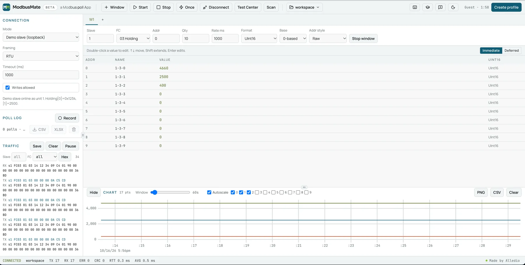
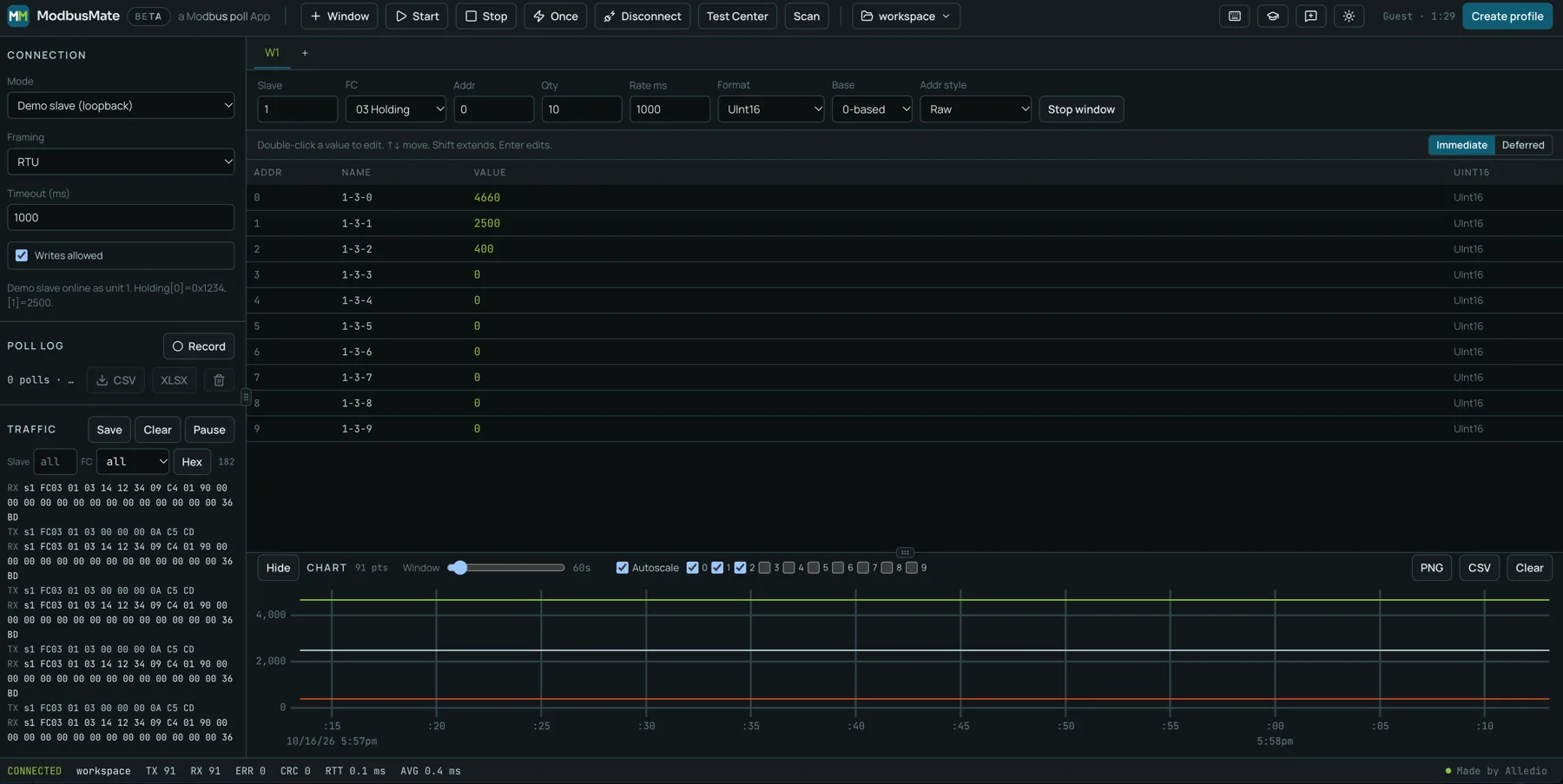
The workspace above is what you see after connecting: the Connection panel on the left, a poll window with the register grid in the middle, and the traffic log and chart below. The status bar at the bottom counts what happens on the wire.
Step 2: match serial settings and slave ID
A Modbus RTU slave answers only when every serial setting matches and the request carries its address. One wrong value means silence, not an error, which is why this step deserves a checklist.
| Setting | What to enter | Where to find it |
|---|---|---|
| Mode | Web Serial for a real device; Demo slave for a dry run | Connection panel |
| Port | Your USB-to-RS-485 adapter | Browser port picker after Connect |
| Baud rate | Often 9600 or 19200; must match the device exactly | Device manual or its display menu |
| Parity and stop bits | 8E1 is the Modbus default; 8N1 and 8N2 are common | Device manual |
| Framing | RTU for almost all field devices; ASCII only if the manual says so | Connection panel |
| Slave ID | 1–247, unique on the bus | Device manual, DIP switches or display menu |
| Timeout | 1000 ms is a safe start for a bench test | Connection panel |
The Modbus specification makes even parity the default, and a device without parity should use two stop bits. Many devices ship with 8N1 instead, so trust the manual over the standard. If the device has a display menu, read the live settings there; field units are often reconfigured after delivery.
Step 3: read a known holding register (FC03) and check the traffic log
Pick a register whose value you can predict: a firmware version, a device type code or a setpoint you can also read on the device's display. Reading something you already know proves the whole chain, from wiring to byte order, in one go.
In the poll window, set Slave to your device ID, FC to 03 Holding, Addr to the register address and Qty to 1–10. Check Base. A manual that says 40001 usually means protocol address 0, so choose 1-based if the manual counts from 1. Press Start, or F5, and watch the grid. When the value matches the display, the device is talking.
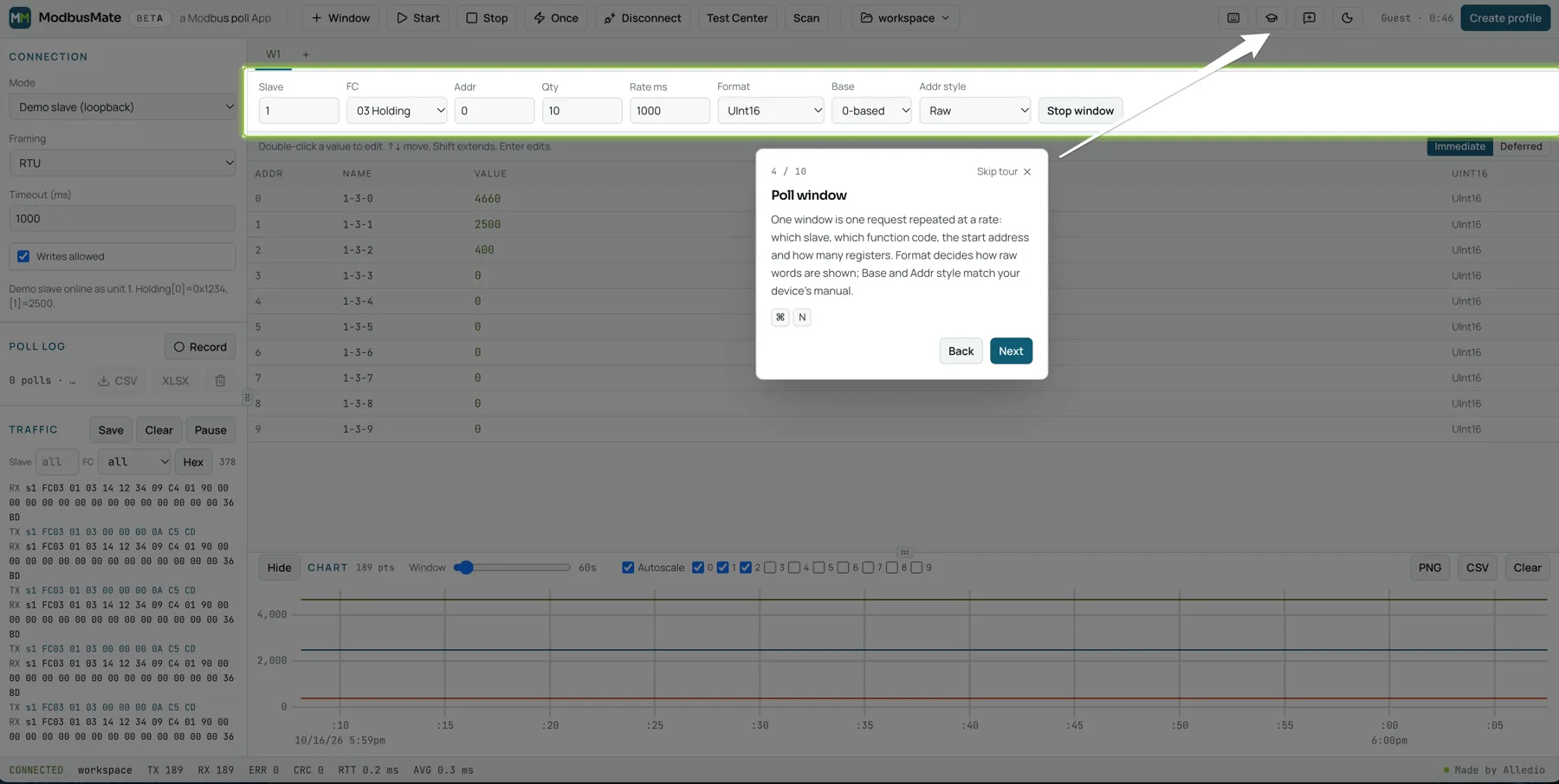
Then read the traffic log once, because it shows what the grid hides. A request to read ten registers from slave 1 looks like this on the wire:
| Bytes | Meaning |
|---|---|
| 01 | Slave ID 1 |
| 03 | Function code 03, Read Holding Registers |
| 00 00 | Start address 0 |
| 00 0A | Quantity: 10 registers |
| C5 CD | CRC, low byte first |
A healthy answer starts with the same slave ID and function code, then a byte count, the data and its own CRC. With the built-in demo slave the reply is 01 03 14 12 34 09 C4 01 90 …: 20 data bytes, where register 0 holds 0x1234 (4660), register 1 holds 2500 and register 2 holds 400. If a 32-bit value looks absurd, change Format to Float32 or Int32 and try another word order such as CDAB.
Now check the status bar. TX and RX should climb together, ERR and CRC should stay at zero, and RTT shows the round-trip time for each request. A rising CRC counter points to wiring or noise, not to the device firmware.
Step 4: write a register safely
Writing is where a test can change a live system, so treat it as a deliberate decision. On a commissioned plant, start with writes switched off: untick Writes allowed in the Connection panel and the session runs in monitoring-only mode, which blocks every write request.
When you do need to write, choose a register the manual marks as writable and harmless, such as a test setpoint. Note the current value first. Double-click the value in the grid, enter the new one and confirm, and ModbusMate writes it to that register. Read it back, check the device reacts as expected, then restore the original value. For multi-register writes, use the Test Center, which builds a raw PDU with presets per function code.
If the device replies with an exception instead of data, the function code in the reply has its top bit set, 0x83 instead of 0x03, followed by an exception code. Code 02 usually means the address is wrong or not mapped; code 03 means the value is out of range.
If nothing comes back: three quick checks
A timeout with RX stuck at zero is the most common first result. Before digging deeper, run three quick checks in this order.
- Swap A and B. It costs ten seconds and fixes a large share of silent buses.
- Confirm baud rate, parity and slave ID on the device itself, not only in the manual. Then try slave ID 1 and the 9600 or 19200 defaults.
- Check that TX climbs and that the adapter's transmit LED blinks. If not, the port or driver is the problem. If your adapter switches direction on RTS, turn on the RTS toggle.
If all three pass and the device still stays silent, work through power, grounding, termination and exception codes one at a time. The Scan function can also sweep slave IDs when nobody knows the address a unit was given.
Building HVAC equipment around Modbus? The Alledio Room Controller, Room Unit and Multi-Sensor speak Modbus RTU on RS-485 and are available as samples with demo or test firmware, so your team can run these four steps on day one. Series supply is OEM only, with an MOQ of 1,000 pcs that is negotiable; see OEM for branding options and Modbus RTU wall user interface for register maps on a wall device.
FAQ
Which register should I read first?
One whose value you can predict, such as a firmware version, a device type code or a setpoint shown on the device's display. A known value proves wiring, serial settings, addressing and byte order in one read.
Do I need termination on the bench?
Usually not. On a short bench lead with one device, the bus works without 120 Ω resistors. On a real trunk of tens or hundreds of metres, fit termination at both ends and nowhere else.
Can I test without the device?
Yes. Set Mode to Demo slave (loopback) and the app answers as unit 1, with holding register 0 at 0x1234 and register 1 at 2500. It is a safe way to rehearse the four steps and learn the traffic log before you touch real hardware.
Does ModbusMate support Modbus TCP?
Modbus TCP is coming soon. Today ModbusMate tests Modbus RTU and Modbus ASCII devices over serial, which covers RS-485 field devices and the serial side of TCP-to-RTU gateways.
Is ModbusMate free?
Yes. There is no licence fee and no paid tier. You start with a five-minute guest session; a free profile with your name and email keeps your workspaces and removes the time limit.
How is this different from a full comparison of Modbus masters?
This guide is a test procedure that works with any master. If you are choosing a tool, read the ModbusMate and Modbus Poll comparison or the ModbusMate launch post.
What to do next
Open the app, run the four steps against the demo slave, then plug in your adapter and repeat them on a real device. Save the session as a workspace, and the next test of the same device model takes under a minute.